 |
Audio Asylum Thread Printer Get a view of an entire thread on one page |
For Sale Ads |
|
|
Audio Asylum Thread Printer Get a view of an entire thread on one page |
For Sale Ads |
47.18.36.115
Can someone let me know if this is sensible?
Follow Ups:
GEO,
The big problem with mesh tubes is they tend to draw more grid current for some reason. The Moth's and other directly coupled amps that did not have good time constants for the power supplies, would tend to push the grid forward when turned off and this would cause the output tube to arc over.
There was tons of stories like this with the EML and other mesh plate tubes. But I think the problem was the design of the tubes. I have a boat load of NOS mesh 45's and never had problems other then just dieing. But the newer ones I had customer problems and tons of people they just died and I don't direct couple them.
I think they are using gold grids now for these tubes to better insulate them from drawing grid current.
Thanks,
Gordon
J. Gordon Rankin
Hi Gordon. I fondly remember you from a show or two...
I had 40 of those AVVT mesh plates. They had hand-picked them over in Germany, so the ones I got were all later types and were nice. (I had bought some of them earlier in the USA, but those were "earlier" batch-- and had the grid problems). They were 100% reliable for me anyhow, but I didn't like their hum levels.
The newer ones had far lower hum, the plant had gone to work to better balance the filament. I suspected that because I was using balanced A.C. to run the filament-- the difference between the two batches was huge.
I have put many thousands of hours on these tubes with zero failures and zero "wear-outs". The plate currents I was using-- I found out later from JAC, were what he always used. About 2/3 "normal". Plate voltage was set up as 490 ON the plate, and 240 on the cathode, giving 250 VDC plate voltage. (D.C. amp).
What I love about these tubes is their transparency. They can SOUND "superconductive".
Kevin Hayes (VAC) had coached me into trying JJ's, which he had fallen in love with (big, rugged, easy to drive, (bold!), powerful sound). Idealize an amp for those and the mesh sounds a little "off", certainly not very "off"-- still more than acceptable in the tube amp world.
I would run those old mesh tubes for thousands of hours, running loud levels (I love it-- it stays clean) just running them hard, cooking, doing dishes, working outside. I just let them run like an appliance.
For shows or visitors, I always had a super-good pair, one that I had hand-picked, balanced in every way, including the resonant frequency tests. Those would have had about 1000-1500 hours on them, (broken-in) and them they were stashed, and only run every 6 months or so, for a short period.
Interesting tube (last batches). Idealize an amp for that tube, and you'll never forget it.
---Dennis---
Do you mean shaking them and listening to what they sounded like to determine if the sound matched?
RFT is used in many industries.We use it in the lab where I work on some of the test gear, heavy industrial applications.
Link to AN 8.1 Microphonic tubes.
If DF does any advanced analysis beyond tapping on the tubes is unknown to me.
Edits: 11/20/14
Is it done by ear?
I've seen DF tap on uninstalled tubes at multiple RMAF shows, with the tube being up to his ear. He seems to know exactly what to listen for !!
Sorta amazes me. I wanted to giggle, but I am sure he is serious.
Jeff Medwin
OK. If you don't have a good mike and a spectrum analyzer present, then you can still do what it takes.
The tube that resonates identical to another, and their currents and internal capacitances are equal also, are a good pair. Is this important in S.E. amps where only one output tube is used? (normally-- one could have parallel S.E.). Sure it is-- you're trying to get one amp to track with the other.
If you have two tubes that have the same internal capacitances and draw equal currents at idle, but they resonate differently from each other, usually because their filaments are different-- one is stretched tighter than the other-- then they will sound VERY different from each other on equipment that is good enough for you to tell!
So--- WHY NOT balance the two channels (in Stereo playback mode) sonically with each other? It sure does sound more coherent when you do.
-Dennis-
So that is why my quad of 45s sounded funny as two pairs I thought were identical were not.
It was only when I matched 1 tube from 1 pair with another that I got magic.
And it didn't correclate with the specs on the boxes either.
The other pair sounds half way between the best I have and the worst I had.
Trust your ears as Jeff keeps telling me.
Smart
Tubes and capacitors! Best thing we can do with both is have a box full of them (in caps, you need different brands as well), and play.
Let THEM tell you what is the correct applications and values. You will have far more useful "data" than just theory to figure it all out with-- later. Keep the Science & Theory HANDY, just don't FALL IN LOVE with it!
I see you're a thinker:
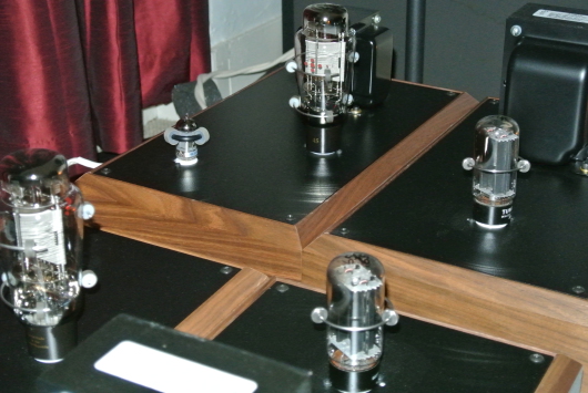
You've seen all the criticism on my old amp on here. Take another look at the picture posted by GSH and see if you can figure out why the main ground bus wire went straight to the IEC socket ground, and why it was routed that way instead of going around the other side of the amp where all the Power transformer A.C. lines are.
People like to make amps look pretty inside. I do what I can and is practical, when that works. Can you figure out why there's a "bird's nest" wherever many capacitors are paralleled? Why are the leadouts (from each cap) not straight, why are they coiled, or bent? (doesn't look as pretty!).
Why are leadouts from the power trans left as tinned-copper, but elsewhere in the amp, a lot of silver is used? How did I get away with a Hammond, unshielded power trans? Why was it used?
Why is so much brass used? What fasteners must be brass, and what ones can just be steel?
What spacing is necessary when you bundle caps, and why is silicone glue used to bundle them? Why aren't they allowed to touch each other-- or be near anything else? (In each bundle, they're separated from each other by glue pads).
Back to the "bird's nest": The photo is 2-dimensional. What is happening in 3 dimensions that is important in mounting parts-- sonically, and, since they can't be allowed to touch anything or be too close to it, what anchors them? Why is the chassis as deep as it is?
Where is most of the A.C. hum in this amplifier coming from, and what efforts were made in later years to cut it back, but still not affect the sound qualities?
What did the manufacturers of some S.E. triodes do in the last 3 years to reduce hum levels?
Why can't Zip-Ties or cable bundling (to look neat) be used to anchor parts or wiring?
What wires CANNOT be anchored or bundled with, or be near-- anything?
What happens when grounds are "dressed" close to the chassis metal, and how is this different from signal-carrying wiring?
What about B+ wiring? How is it different from the other two?
What happens if one of my old amps falls off a table onto the floor-- and what protects them if one does? How does this relate to shipping them around, using UPS or FEDEX?
What happens when even the best of modern capacitors are used to bypass a cathode "fully" (that is with both the cathode resistor value and the tube's calculated "resistance" rolled-into one, and that figure used to determine the cap's value). What happens sonically?
What can you do to inch closer to the calculated cathode cap value and get away with it sonically?
If you put two resistors in series on the cathode, and bypass only one of them, why will that "sound better" than having only one resistor fully bypassed?
What is there about putting two resistors in "the tail" (cathode) in series, and bypassing only one of them that will wreck your signal linearity and timing accuracy on Hi-Eff. speakers? Why can't you get away with this, and what works vastly better?
These questions are open to all members-- GSH opened things up, so let's figure it out.
I like your system ideals, and I think you're going to be a Happy Camper!
---Dennis---
The problem is Dennis, you don't know the answers yourself. And what theory you do post is hogwash to anyone with an engineering background - no matter how it was obtained. IOW,it's not just the professional engineers here that debunk your fantasy. It's most of the experienced and competent hobbyists as well. Anyone who knows how these circuits actually work see through all your hype.P.S. And no matter what sonic benefits you think you reap with your IEC ground wiring, I can tell you it's not approved by UL or any other world safety agency. You are not permitted to ground primary power in that fashion.
Edits: 11/21/14
LMAO, first you say "good questions", and then....."DF doesn't know".
What you failed to realize, conceptualize, is that DF has already asked ALL these questions to himself, likely years ago, and found the answers that worked well for him. He was simply "opening up" the conversation on this Forum to people who wanted to discuss it, in a legitimate non-offensive way .... on a higher level than what we generally see in this thread.
Are Nuns all just whores to you Gusser?? Is white really black, and red really blue ??
Jeff Medwin
I'll bet he has some input to add when it come to the electrical engineering skills you and Fraker posses.Let's get another professional opinion on this build.
Edits: 11/21/14
Henry's no problem, except for his bias and dislike of DF ( and I ) which clouds his even-handedness.To his credit, it was Henry who very nicely explained the superior regulation obtained by a less than L-Critical L1.
Search word is Flywheel. Its a real shame hes never been to a show, etc. to hear the amps perform. Same for you, countless others.
Jeff Medwin
Edits: 11/21/14
Not seeing exactly where the IEC ground is connected to the chassis.
Perhaps the photo does not show it clearly.
What problems are you finding, Gusser?
1) It's not good engineering practice to run a dirty AC line ground back right through the input stage components. Furthermore UL and European codes dictate the power safety ground must be bonded by a dedicated purpose means. That means it cannot share with any other wire or component mounting means. Now we surely don't have to follow that rule for DIY but Dennis sells these amps to the general public. They should at least meet the basic electrical safety standards.2) The negative side of the main filter cap bank is also run back under the input stage. This lead will have substantial 120hz spikes from the rectifier action. Now the use of a tube rectifier does tame these pulses quite a bit. But it's not good engineering practice at all.
But it still might work fine in this amp. Ground loops and EMI/RFI are quite difficult to thoroughly analyze. Even experienced RF engineers as is my area of study, often joke about the witchcraft needed to tame EMI/RFI. But be assured it can be done through mathematics.
So Dennis either got lucky, which is very possible, or there is 120hz buzz on his output.
Also keep in mind that the LSES is deficient in it's filtering ability. So the additional 120hz buzz due to this poor lead dressing may in fact be masked by the amps poor PSRR.
Edits: 11/21/14
The IEC ground wire is firmly bonded to Chassis metal BEFORE it goes anywhere else.
You don't see that in the photo. Your claim is understandable-- from just looking at the photo, but it is wrong-- safety has always been the first concern-- circuitry comes second.
In other words, chassis cannot be disconnected from IEC ground regardless of any component failure(s).
---Dennis---
A
Exactly. But it's good to understand why. Easier to duplicate if you like that kind of sound. Like changing the tint setting on your tv. Good to know where your settings are when using tone controls.
Maybe he could share what he is listening for with the rest of the world. Thanks.
See above, he does.
Jeff
Must have good hearing.
Thanks Gordon. I hope life is good in the Queen City. I recall those AVVT 2A3 problems. I was just trying to make heads or tails out of the explanation for why mesh plates sound good. I used to use mesh 27 and solid plate philco 27s. I preferred the ST philcos even after I got around the microphonics in the globe mesh 27s, but to each his own, unless you disagree with a couple fellows here.
Do electrons exist? Are electrons actually moving from cathode to anode if they are negatively charged? Is it better to think of photons moving around, ie energy without mass.
Don't think of physical particles but more energy.
I'm convinced, built a DC45 amp and awaiting my EML Globe tubes in the new year.
EE are the worst amp builders, too rigid in thinking. They need to expand their minds and approach design from a different angle. Plus, anything under 100dB efficiency is just a blanket to music.
$10K in parts so far and you wonder why they charge so much. Cheap if you ask me.
Free your mind, free your music.
Go see Interstellar, the ending in the multi parallel library looks like the inside of a tube. There are ghosts in those meshies.
"Do electrons exist?"
Yes they do.
"Are electrons actually moving from cathode to anode if they are negatively charged?"
You might be a little confused.
What we call B+ is a bit of a misnomer.
We call it "positive" voltage because it is lacking in negative charge.
When the plate of a tube has a "positive" charge that means it is lacking in the number of negatively charged electrons that it would take to make it neutral.
So yes, electrons are actually moving from cathode to anode because they are negatively charged and the plate is positively charged (missing or needing electrons).
And those electrons go right through the power supply to ground and up through the cathode resistor right back to the cathode again.
It's just fascinating, isn't it?
Tre'
Have Fun and Enjoy the Music
"Still Working the Problem"
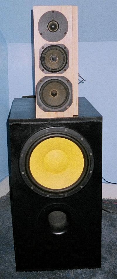
I don't have a crossover in my speakers.
Smart845
It isn't the efficiency that is the issue IMO.
It is the inductors in the crossover
that is the blanket to the sound.
Driver is critical in the design though.
Not all midbass' can be run full range.
They need a smooth roll off.
DanL

Your speaker drivers have inductors too - the voice coils moving about a central iron core. You also have inductors in your amplifier - the primary winding of the output transformer or plate choke. Inductors are not the problem. What you hear as greater clarity without a crossover inductor is most likely a rising, non-flat frequency response from your speakers.
I disagree ...
What I hear is the lack of control
of the speaker diaphram with an
inductor or a resistor in the crcuit.
The inductor that is in the amp and
in the driver are vastly different than
the one in a crossover electronically.
That's like comparing apples to dump trucks.
DanL
No doubt series resistance and inductor DCR decreases damping and increases Qts. However sealed boxes are pretty forgiving this way, from my experience. Of course you don't want excessive resistance but 5% of the speaker impedance shouldn't be audible.
I still believe from my experience that what you are hearing and liking is a rising frequency response. Every speaker of medium to narrow baffle has this. This is the same argument full range single driver proponents state but fail to measure the frequency response of their system to see it is far from flat.
The DCR of the inductor coil as a crossover is between the amplifier output and the driver and thus lowers the damping factor (adds resistance to the output impedance).
That, IMO, is a valid concern.
I use midrange speakers that do not play very low and are heavily self damped and I don't think a small amount of DCR in the inductor coil would make much of a difference, but with other drivers this could be a valid concern.
Tre'
Have Fun and Enjoy the Music
"Still Working the Problem"
Tre'
My Audax drivers have a Qts
of .25 (5.25") and .54 (4").
They only go down to 200Hz.
When I dropped the inductor
the details went from good
to just plain amazing.
I used a Goertz 12ga copper
ribbon inductor so no slouch.
My woofer has a plate amp so
no iductor there either.
DanL
Have you measured the FR with and without the coil?
My JBL has a QTS of .35 and I don't hear any difference in the bottom (also limited to 200Hz) when I remove the coil but I do hear the response above the 2500Hz crossover point increase.
That can give a sense of increased detail.
Tre'
Have Fun and Enjoy the Music
"Still Working the Problem"
Tre'
I did need to decrease the tweeter cap
to compensate for the extended range.
From ~4K to ~6KHz to be more precise.
Once I did, the difference was awesome.
Vocals were more clear and distinct.
Guitar and piano had better tone.
Transients and decay were more natural.
I got the idea from listening to some
Reference 3A speakers at a show.
I never thought that I could duplicate it.
I was amazed that I did.
DanL
That's cool.
My conclusion, from what you are reporting, is that the range from 4kHz to 6kHz is better served by the mids than the tweeters.
What tweeter is that? It looks like a Morel MDT33.
I have 3 pairs of those.
It is a little surprising that your mids would be better in that range than the tweeters, but I won't argue with you.
Tre'
Have Fun and Enjoy the Music
"Still Working the Problem"
Tre'
Not Morel even better - Dynaudio D260.
No way would I ever think anything
outperforms the Dynaudios.
My brother preferred Morel
but I loved the Dynaudios.
That was before he found Magnepans.
I heard them first and realized
that this is what he would love.
I even said once he heard them
that he would scrap his speakers.
And that's what he did.
Now he's the moderator
on the Planar Asylum.
DanL
OK, what is your alternative explanation for the audible superiority of the AVVT mesh plate over all other 2A3 tubes. No guessing, speculation, or voodoo science?
Observe, before you think. Think before you open your yap. Act on the basis of experience.
Two comments:
First, Paul Joppa posted some comments a while back (may be a couple years ago) about the rationale behind mesh plates and that it had to do with offering some cooling for the grid.Second, I owned for a while a NOS quad set of the AVVT 2A3M with the blue glass. I tested them in my Amplitrex tube tester and they measured far from the standard 2A3 specifications, drawing much higher plate current for one. It would be interesting to test your pair and see how they measure.
Edits: 11/20/14

Could it be that it really is not a 2A3? It is not a 2A3, it is a unique DHT tube that can be operated with 2.5 volts on the filament. Is that a bad thing? no, it is not. What you like about it is that it has headroom and a distortion/frequency response/impedance that is pleasing.
is "because they cost more" the right answer? I am not an engineer but here is a go at it. Let me know what you think.
I suspect that the osmosis in the plates results in a higher absorbtion factor simply because there is discontinuity and less unform plate structure for some of the electrons to energize. The assymetrical structure provides for some discontinuity in the resonant frequencies.
This gives you an amalgamation of different kinds of energy releases and in turn results in different sonic artifacts. These artifacts can be additive to the main signal, and make music sound euphonic. But keep in mind, the signal may also be distorted in many ways which are audible on very sensitivity transducers.
I can't discriminate between babble and science. I'm an economist. I only know what my brain tells me: the AVVT meshplate is the best sounding 2A3 tube i ever heard, including the old National Union- and Cunningham-RCA single plates, not to mention either of the 2A3 EMLs.I'm always told "it's the materials". Who really knows. Dennis? Jac? Who?
Observe, before you think. Think before you open your yap. Act on the basis of experience.
Edits: 11/18/14
I am glad you see Dennis and Jeff the way I do. I majored in Economics in college actually.
nt.
Although I have trouble with the concept that music qualities (not distortions) are influenced by the way electrons bounce around. I keep my mind open :> )
There is something to be said for the manipulation of electrons to provide uniform flow from Cathode to plate. All valves with more than 3 elements are the result of trying to get maximum uniform electron flow. The suppressor grid is used to slow electrons down to minimize bouncing off the plate and creating distortions. The Beam Tetrode uses plates to control the profile of the electron flow and so on...
Stuben
If you want to be open minded then why not do the research in electrical engineering to learn how electrons travel through materials.
Now for somebody just starting out I agree that could take years.
So why not listen to those of us that have that training and experience rather than someone with no accredited background whatsoever in the subject.
How many electronics professionals here support Dennis's theories? What does that tell you.
then make my design/ build decisions on a range of factors. I am willing to play it by the book, listen to the EEs I find credible; I am also willing to experiment.Frankly, as a past Research Manager and someone now responsible for a team that provides critical data for research projects, I find the arguments presented here and in the thread below unconvincing.
Would you suggest that the credibility of "those of us that have that training and experience" has been enhanced by the comments posted to this thread by the main protagonists? Do you think that the methods, arguments and behaviours demonstrated here and below have earned you the privilege to be considered worth listening to? What value do you think you have added beyond appealing to the like-minded? Frankly, if you want to be listened to - to be heard - as you suggest, you need to lift your game.
I will regret posting on this topic, in this manner, but there it is.
Cheers.
"In the beginner's mind there are many possibilities, in the expert's mind there are few." Shunryo Suzuki
Edits: 11/19/14 11/19/14
Gentleman or %^&hole doesn't matter. Scientific facts are what they are.
You may prefer conversing with the layman gentleman versus an arrogant engineer. But be careful who's opinion you put your hard money on.
Your response confirms exactly my point: it seems almost entirely unrelated to what I posted. If your interpretations are far removed from reality, what is the point in continuing a dialogue?As for "facts", you don't simply post them. If they are absolute and should just stand, why not just post them with a simple explanation and move on?
You need to do better or stop.
Cheers.
"In the beginner's mind there are many possibilities, in the expert's mind there are few." Shunryo Suzuki
Edits: 11/19/14
But I think what you are trying to say is that I and possibly a few others here don't project an aura of credibility based on our hostile nature towards the Serious Stereo drama.OK, then people can ignore any or all of my advice if they choose.
This Serious Stereo amp has been rammed down our throats for years by LowMu. And talk about poor sportsmanship! LowMu has been very insulting to people who don't embrace his thinking.
So now we finally see the truth, the underside of this so called perfect amplifier and what do you know, it looks exactly like we expected. Just like many other hobbyist builds. Not bad but nothing special either.
If Dennis would simply say HE thinks his amps are the best and even offer some personal theories of why, nobody would be put off. But he chooses to dictate this junk science which is easily disputed by many people here.
If you think his ideas are worth your investment of time and money, then go for it. This is a hobby site. I don't care. I have a highly successful 30 year run in electronics, that would be the TV broadcast industry. I also hold senior IEEE membership, which requires accreditation and/or demonstrable experience measured by my peers.
So if you don't think I or anyone else who dares to challenge Dennis here is credible than don't. My technical competence and credibility are already established by several professional societies. I really don't give a hoot if the SET forum, Dr LowMu, or Dennis Fraker thinks otherwise.
Edits: 11/19/14 11/19/14 11/19/14
How could you be credible if you say "wire" does not make a difference in audio? We are in the DARK ages here - with you, a graduate EE.
And how can you be called "professional" using the terms you do ......"polished turd" comes to mind.
And, have you ever gone to an audio show to HEAR said amplifier, so you can speak from your direct LISTENING experience??
I've said all I care to.
Jeff Medwin
I didn't say wire makes no difference in audio. Surely the wrong type or gauge of wire in any electrical application can make a difference.What I did say is that I could replace any of the silver hookup wired in the Serious Stereo 2A3 amp shown with 18ga door bell wire from Home Depot and it will not sound any different. Nor will it measure any different using standard electrical tests.
There are simply no laws of physics that can substantiate an audible difference between door bell wire and the most expensive silver wire at those distances, signal energy levels, and application. Nothing!
You may quote the last two paragraphs at will.
Edits: 11/20/14 11/20/14 11/20/14 11/20/14

I have to ask, how in Dennis' world view is the stock wire, used on the lead outs for the secondary (including center tap) of the filament transformer winding, any better than what is being referred to as "the wrong wire"?
To anyone answering this question, keep in mind that those wires are in the signal path as is the wire between the plate of the driver tube and the grid of the output tube or the ground buss wire.
Are those wires somehow better than the "ACME wire, sourced from Lowes Hardware stores" that Grant used and was told that "one inch of the wrong wire can totally ruin the sound of an amplifier"?
There's no technical consistency in Dennis' argument, just a bunch of BS.
It's not just that I disagree with him technically. Dennis disagrees with himself technically.
Tre'
Have Fun and Enjoy the Music
"Still Working the Problem"
It looks to be a stock filament transformer, so I doubt the wires are anything more than stranded copper.
Perhaps this part has been upgraded/replaced by something better.
"Perhaps this part has been upgraded/replaced by something better."
I would assume so and Dennis confirmed that below.
My point is, at the time the picture of Dennis' amp was taken he was using the stock lead outs.
I don't personally think that those short leads would make any audible difference to start with but then I'm not a big "believer" in wire differences.
IMO, If 'one inch of the wrong wire ruins the sound of the whole amplifier' then the design of the amplifier sucks and needs to be re-designed.
Tre'
Have Fun and Enjoy the Music
"Still Working the Problem"
Of course it has been.
I got into pulling the leads out of chokes & transformers and replacing them with Siltech wire.... I do that to speaker drivers as well, and to a whole lot more. This, of course, greatly improves their bandwidth and impulse response.
(Open up a JBL horn-driver, re-wire it with Siltech and THEN listen to the highs!). Use WonderSolder!
Dr. low mu, then, brought that idea (of replacing leads with TCSS, etc.) to you all so you could get more out of-- especially-- ordinary, commercial chokes.
I have had some chokes built to my specs lately-- they have silver leadouts designed-in. (more expensive).
These are very nice, but one can, if sufficiently handy, modify commercial chokes and get very good results. Leadouts can be re-anchored with G.E. Silicone-2. Let it cure thoroughly before you pull on that new wire!
Also, while inside the choke's insulating materials, make sure you re-insulate your new wiring against the winding stack-- just depending on its insulation alone won't make the choke reliable in long-term use.
---Dennis---
Many moons ago, I owned Spendor 9A. I decided to modify the existing stock zip wire that connected the drivers and replaced it with high end speaker wire.
Thanks for falling on your own sword, and hanging yourself, in just two quotable paragraphs. Shows how misinformed you are !! No fixing you. Nice job Gusser !!!
Jeff Medwin
Have you heard Gusser's amps? How do you know they don't sound better than yours? How do you know? Have you sat down and listened to them? Can you speak on Tre's amps from direct LISTENING experience? Just say you like how your amps sound and move on. If the amps can't be duplicated without pixie dust, then something is wrong.
I've seen Gusser's amps, and his build, and can imagine what it would be like.
I have used power supplies that are conventional, by the book, and I know what they do to the music.
They ( those two people ) have NEVER tried or heard what I have !!!
I speak from experience with BOTH approaches George, so, I am better prepared from an experienced point of view, direct experience, not guessing, and guessing-wrongly to boot.
There is no pixie dust, that is in your Grand-Kids' comic books. I do solid stuff in audio !!
Jeff Medwin
I thought someone here said, its not the schematic, but its the builder?
Just to set the record straight, I have tried both approaches.
I speak from experience with BOTH approaches.
Not only have I listened to both, I have bench tested both.
Tre'
Have Fun and Enjoy the Music
"Still Working the Problem"
A good Con has some kernels of truth.
That is all you need to know.
Tubes are about settled electrical principals of conduction and dissipation. No one needs to guess. It is why we have things like tube curves.
It is the most make believe of all the posts I have ever read. I can see why people who listen to him are prepared to drop $15k+ on his amps.
Oh no no, you still get it all wrong. Everyone I know, who owns his amps, FIRST listened not to Dennis, but rather, to Dennis' amps, and as a result, made a very easy decision.
Jeff Medwin
Alchemists, Spiritualists and Wizards were (are) revered. Frauds, but revered for how they make people feel. The mark that does not know he is a mark is technically unharmed if he believes in the con.
Alchemists. I love it.
Post a Followup:
| FAQ |
Post a Message! |
Forgot Password? |
|
||||||||||||||
|
||||||||||||||
This post is made possible by the generous support of people like you and our sponsors:
