- Posted by Lynn Olson (M) on December 05, 2003 at 15:50:06
In Reply to: Assorted Thoughts posted by Lynn Olson on December 05, 2003 at 14:21:20:
Some data from John Atwood (my predecessor as Tech Editor at Vacuum Tube Valley, and now head of One Electron) indicates that a current source enforcing balance on a PP output stage can raise 3rd harmonic while reducing even harmonic magnitudes to near-zero.My guess for what's going on is that with a current source in operation, the PP stages are effectively in series; while with a low-impedance cathode return, they are in parallel. In Class A, this should make little difference, except for the effect on instantaneous output impedance.
If you were to plot instantaneous output Z versus output voltage (as measured at the speaker terminals), for series connected tubes I'd expect to see a plot in the shape of a U-shaped valley. With two devices connected in series, the higher-value one is going to dominate, especially as one power tube heads towards cutoff. For example, as you approach the cutoff condition, one tube might look like 3K, while the other looks like 200 ohms. In a series circuit, the high value will dominate, resulting in 3.2K. So as the circuit as a whole approaches saturation, the impedance rises, and it eventually cuts off completely. It behaves exactly like two SE amps connected in bridge-mode. All of the SE 2nd harmonic properties are translated into 3rd harmonic, since both SE amps are symmetric, but driven in opposite phase.
But things are completely different with a parallel circuit (conventional PP in Class A). One tube looks like 200 ohms, while the other is 3K, but 3K in parallel with 200 ohms is 187.5 ohms. If you plotted this out, you'd have a more or less flat-topped plateau, with sides that sloped downwards (not up) on either side. However, the flatness of the plateau might be critically dependent of the bias value - I can easily imagine little ripples around the center and the sides as the standing current is moved up and down.
Interestingly enough, in a preamp, input, or driver, this variation in impedance is not that important, since the load impedance is much higher than the source impedance. But in the final power stage, the load is our old friend, the loudspeaker, which is intrinsically reactive, and even transmits resonant back-EMF energy back to the amplifier. This is where the output impedance characteristics start to make a difference, especially the instantaneous impedance as the AC cycle is traversed.
One little challenge I've thrown out to Gary Pimm is devise a simple circuit that will make a plot just like I've described - instantaneous output Z versus plus/minus volts, with adjustable gain in the vertical axis.
A tester like this should instantly reveal the true operating mode of any amplifier - SE, PP, transistor, bridge-mode, Class A, Class AB, feedback, no feedback. All feedback would do is flatten the curve, but it could do nothing to change its shape - that is set by the topology and standing currents of the output stage.

Follow Ups:
- An aside your thoughts suggested... - JamesD 05:16:45 12/07/03
(7)
- In Reply to: Mo' Thoughts posted by Lynn Olson on December 05, 2003 at 15:50:06:

Hi Lynn,
I need to think some more about what you have written before a proper reply. It's interesting and it has stimulated various ideas for me to pursue.
However one thought that did occur to me was a solution I have been trying to find to a very low capacitance balanced input that I wanted to build from triodes. The reason for the low capacitance requirement was the usual, I want to use a 11:1 fully balanced stepup transformer and the input capacitance gets a bit hairy when multiplied by 121 times! Even pentodes can be a bit heavy with this input trannie. However if we take two diff pairs and construct them from a pentode on the input side in cathode follower mode into the CCS tail and a common grid UHF triode on output side then we get - to some degree - the best of both worlds. Using two of these with the triode anodes feeding a PP interstage completes the picture. The triode distortion characteristic and sound would dominate and balance between the two diff pairs is acheived by tweaking the CCSs. I hope the picture above conveys my thinking... Maybe this would work as a low capacitance front end for the Amity? When I get time I think I'll knock this up, I guess I need pentodes and triodes that bias up to similar points...
ciao
James
- Here's another one ... - Lynn Olson 17:34:23 12/11/03
(2)
- In Reply to: An aside your thoughts suggested... posted by James D on December 07, 2003 at 05:16:45:
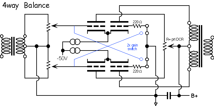
Here's another variation to minimize input capacitance. It takes advantage of four identical triodes - in theory at least, each "side" should consist of one composite device, a cathode-follower with a grounded-grid amplifier. There should be some cancellation of device nonlinearity since they are effectively in a totem-pole configuration, like a folded cascode.
Input capacitance is the same as a cathode follower, only a few pF, about half of which is socket capacitance. Output impedance of the amplifier is probably double that of a standard circuit.The blue lines show an alternate connection with twice the gain, since all grids are driven. This removes the capacitance cancellation, but does give twice the gain of a standard amplifier. I have no idea what the output impedance is ... I leave that as an excercise for the reader. Maybe the same as the other circuit.
Note current balancing feature ... if the resistance of the pot is the same as the DC resistance of the primary on the output transformer, each plate sits at the same voltage, and the pot trims the current going through each "side."
Kinda pleased with this one - have fun, Gary P and JamesD!
- Re: Here's another one ... - JamesD 12:39:27 12/14/03
(1)
- In Reply to: Here's another one ... posted by Lynn Olson on December 11, 2003 at 17:34:23:
Hi Lynn,
Nice circuit! I really like the balance feature. I'm still thinking through the 'composite device' operation. I think I'm starting to see it. One thing is for sure this is a lot easier to set up correctly than my circuit! However Gary P.s suggestion of using the screens to bias and balance the pentodes does work well. I guess the next step is to design a hybrid with a FET as source follower into the grounded grid. Then it's just make them up a try them in different circuits to see which works best... Actually this sure is fun. Thanks for the inspiration!
I've got to make up a couple of guitar amps before Xmas - so playing with this will have to wait but as a teaser, I have knocked up my front end and used it in my fully balanced 6B4G amp and it is better than the previous 6N6P front end. I used EF83 pentodes and 6AM4 triodes.
ciao
James
- Unusual behavior from grounded-grids ... - Lynn Olson 14:59:23 12/14/03
(0)
- In Reply to: Re: Here's another one ... posted by James D on December 14, 2003 at 12:39:27:
One to remember when working with grounded-grid circuits is the GG actually multiplies any impedance appearing at the cathode (input node) by the mu of the tube, so a source Z of 75 ohms is going to look like another 1650 ohms at the plates of an ECC99/7119, giving a total of 3300 ohms per side. This is double the normal output impedance of a ECC99/7119.
Further, any *nonlinearity* in source Z (from the cathode follower) is *also* multiplied by the GG stage, which is then cross-multiplied by the nonlinearities of the GG stage itself. So the overall transfer characteristic is a composite device, and no longer really a single triode. So it's not all obvious what the distortion characteristic would be, much less a pentode/triode combination!
By the way, the pentode cathode follower will have much less output impedance if the screen is cap-coupled to the cathode - since the screen acts like a virtual plate, that improves PSRR, and also reduces distortion since the effective plate voltage is closely tracking the output voltage instead of B+. Think of it as a cascoded cathode follower and you'll get the idea.
You still have to feed the screen current, of course, but that can done with a simple screen-balancing pot like in Gary Pimm's PP47 amplifier (see R18 and R20 on the last schematic linked below).
For the all-triode version, a 220-ohm carbon-comp grid stopper needs to be added on the GG triode (right at the grid pin of the tube socket, and between the socket and gain-switch). These are very very fast circuits, and capable of oscillating at 20-50MHz given a chance. GaryP recommended 1K for pentodes and 220 ohms for triodes, which makes sense to me. Fortunately, the high/low gain switching is click-free and benign, since the grids of the GG stage are at zero DC potential (the 2X gain-switch works for your circuit too, by the way).
- Unusual behavior from grounded-grids ... - Lynn Olson 14:59:23 12/14/03
(0)
- Re: Here's another one ... - JamesD 12:39:27 12/14/03
(1)
- It boils down to a pentode CF driving a GG triode - Lynn Olson 13:56:45 12/07/03
(3)
- In Reply to: An aside your thoughts suggested... posted by James D on December 07, 2003 at 05:16:45:
Which looks perfectly good to me - in a way, a close relative to Gary Pimm's circuit, but also completely different! Each "side" is operating independently of the other, so it still looks like a pair of SE amps in bridge-mode, and as far as I can tell, the output triodes are in series with each other. If the input pentode was removed from one side, the whole output stage would shut down. I can't immediately see any way to have the output stage operate in parallel, although this may not be that important.
Linearity would be very good, though, with a cathode-follower pentode (by far the most linear CF) and a grounded-grid triode. It is an elegant circuit, all right.
- Re: It boils down to a pentode CF driving a GG triode - JamesD 08:27:07 12/09/03
(2)
- In Reply to: It boils down to a pentode CF driving a GG triode posted by Lynn Olson on December 07, 2003 at 13:56:45:
Yep, it does indeed. Thank you for expressing it clearly. It was your observation that a diff pair with CCS is working as two SE stages in series but summed through the induced field in the transformer that provided the 'flash of light' for me. I then confused the expression of the idea...
I'm working on exactly how to set the bias point for the CFGG pair - I think I may end up with a combination of fixed bias and CCS to get the right conditions for each device.
John Atwood's data makes sense if the devices are in series. In the summing node the even harmonics cancel but the odd harmonics would add just like the fundamentals add - that's conventional PP. Then as the dynamic balance forces better cancellation of 2nd harmonic so it must force better addition of third harmonic (I guess we should see better addition of fundamentals too).
I don't think this will actually sound better as I believe we need to ensure a smooth roll off of distortion harmonics for the best sound. Given that the ear/brain system is working as an 'inverse FFT' analyser i.e. it is taking all the complex spectrum structure that the ear generates and analysing this to extract tones/notes from the complex harmonic profile - then it is important that we maintain a harmonic profile that is consistent with the ear/brain analytical mechanism or risk the likely hood of 'distorting' what we hear... So maybe the use of CCS and pursuit of ever better dynamic balance is not a 'good thing'? This is consistent with my experience in that I tweak my PP stages for best sound not actually best balance...
Of course the best thing is not to generate distortion in the first place so maybe the CFGG configuration will catch on as it's linearity looks very good!..
ciao
James
- Setting up the bias - Gary P 12:00:45 12/10/03
(1)
- In Reply to: Re: It boils down to a pentode CF driving a GG triode posted by James D on December 09, 2003 at 08:27:07:
Hi James,
"I'm working on exactly how to set the bias point for the CFGG pair - I think I may end up with a combination of fixed bias and CCS to get the right conditions for each device."
One way you can get the pentode and triode to have the same grid bias is to make the screen voltage on the pentodes independantly adjustable. At a fixed current, rasing the screen voltage causes the grid bias of the pentode to increase. This can be used to balance the triode/pentode pair.
If you need more bias range than that, thinking of a hi GM pentode with low bias needs and a low mu triode with hi bias needs, you could as you mentioned use some fixed bias on the center tap of the input transformer secondary and still vary the screens to match each pair.
In the 47 amp I have been using the input screens to balance the amplifier with good success.
Tektronix used the same technique (thats where I got the idea from) in some of the scope front ends. The circuit description from Tek described this technique as a way of matching the grid to cathode voltages of the pair of pentodes.
Best regards,
Gary
- Re: Setting up the bias - JamesD 03:50:58 12/11/03
(0)
- In Reply to: Setting up the bias posted by Gary P on December 10, 2003 at 12:00:45:
Hi Gary,
Many thanks for the pointer. Your right to assume that I had mentally fixed the screen voltage once I had chosen a point from the tube curves! Your 47 amp should have knocked my thinking out of that groove - but it hadn't so your post is most welcome.
BTW I really like your new front end - but I'll post my comments over in the right thread.
Thanks again.
James
- Re: Setting up the bias - JamesD 03:50:58 12/11/03
(0)
- Setting up the bias - Gary P 12:00:45 12/10/03
(1)
- Re: It boils down to a pentode CF driving a GG triode - JamesD 08:27:07 12/09/03
(2)
- Here's another one ... - Lynn Olson 17:34:23 12/11/03
(2)
This post is made possible by the generous support of people like you and our sponsors:

You can not post to an archived thread.
[
[ General ] [ Speakers ] [ Tubes ] [ Vinyl ] [ Digital ] [ Hi-Rez ] [ Video Asylum ] [ Cables ] [ Tweaks/DIY ] [ Music ] [ Films ]