Hi Brian,
I recently picked up a Denon DVD-2900 universal player, and I've got the urge to tinker with it a bit.
I'd like to bypass the opamp outputs and come up with a better sounding output stage.
The CD player uses a DSD1790 DAC chip, very similar to the DSD1792.
It is a differential, current output chip...see the spec sheet below.
From what I've read, this DAC chip is almost identical to the PCM1794.
I read through the installation manual, but I'm not positive...
Will your 'Universal Tube Output Stage' work with this DAC chip?
Thanks in advance,
Mike
Follow Ups:
- RE: DAC Output Stage - a few questions on implementation! - bcherry 16:24:24 12/30/09
(11)
- In Reply to: RE: DAC Output Stage - a few questions on implementation! posted by Mikey on December 29, 2009 at 20:24:44
Yes. A configuration for the PCM1794 is covered in the manual as linked.
The wiring diagram is on page 22. This is for a balanced outputs and requires two Universal Tube Stages.
For single ended output simply only connect the negative outputs from the the DAC to the UTS and connect the unused current output to ground via 22 Ohm. Only one UTS is then required.
DIY - Done Right!
- RE: DAC Output Stage - a few more questions.... - Mikey 16:54:44 12/30/09
(10)
- In Reply to: RE: DAC Output Stage - a few questions on implementation! posted by bcherry on December 30, 2009 at 16:24:24
Hi Brian,
Thanks for the reply....a few more questions:
It seems I could choose one of two ways to implement the UTS with my CD player:
1. Obtain (1) UTS, and wire it as described in your previous post, with the 22ohm resistors to ground.
Are there any ill effects to utilizing the DAC chip this way?
2. Obtain (2) UTS, and wire them as described on page 22, with balanced outputs.
Page 10 shows the balanced output wiring, and it seems as though I can produce BOTH a single ended and balanced output in this configuration.
- Have you ever compared the two (single ended output) schemes?
- If so, which did you prefer?
- Is there a theoretical advantage to scheme #1 vs. #2?
- Is the kit with power supply in stock?
- How long is delivery to the U.S. (CT)?
Thanks for your help thusfar,
Mike
- RE: DAC Output Stage - a few more questions.... - bcherry 21:17:09 12/30/09
(9)
- In Reply to: RE: DAC Output Stage - a few more questions.... posted by Mikey on December 30, 2009 at 16:54:44
> It seems I could choose one of two ways to implement the UTS with my CD player:
Yes.
> 1. Obtain (1) UTS, and wire it as described in your previous post, with the 22ohm resistors to ground.
> Are there any ill effects to utilizing the DAC chip this way?
In all the cases it was tried previously, no. It is of course hard to be absolutely certain about each and every DACIC in the world or to test them all to be sure.
> 2. Obtain (2) UTS, and wire them as described on page 22, with balanced outputs.
> Page 10 shows the balanced output wiring, and it seems as though I can produce
> BOTH a single ended and balanced output in this configuration.
Yes, this will produce both Single Ended and Balanced output's in the manner that is standard for HiFi gear.
> Have you ever compared the two (single ended output) schemes?
Not directly, however the actual performance will be for all intents and purposes identical, as for the Single Ended output the effective circuit is mostly the same.
> Is there a theoretical advantage to scheme #1 vs. #2?
The key advantage is that you only buy what you need. If you eventually intend to use Balanced Outputs implementing # 2 obviously gets you ready for this. If you always want to use only single ended outputs implementing # 1 will get you the same performance and will allow you some extra cash to spend on the best quality RCA Jacks and Cables etc.
> Is the kit with power supply in stock?
Yes, it is, for either Stereo Single Ended or Stereo Balanced configuration and can ship within 24 Hours - business days.
> How long is delivery to the U.S. (CT)?
Fed-Ex 3 or 4 days. Mail package post 7 - 10 days.
DIY - Done Right!
- DAC Output Stage - order placed! - Mikey 08:13:26 12/31/09
(8)
- In Reply to: RE: DAC Output Stage - a few more questions.... posted by bcherry on December 30, 2009 at 21:17:09
Hi Brian,
I ordered the kit today, I decided on (1) UTS.
It was going to be tough to shoehorn two of those modules in there anyway... :-)
The only thing to clarify is the wiring between the DAC chip and the module, let's see if I've got this close:
DAC pin 26 (L-) to UTS terminal 'in L'
DAC pin 25 (L+) to 22 ohm resistor, resistor to GND
DAC pin 18 (R-) to UTS terminal 'in R'
DAC pin 17 (R+) to 22 ohm resistor, resistor to GND
In the Denon schematic, all four AGND pins (16, 19, 24, 27) are tied together....this will be my analog ground, correct?
If correct, let's call this GND.
GND to UTS terminal 'Gnd L'
GND to UTS terminal 'Gnd R'
GND to UTS terminal 'Vcom L'
GND to UTS terminal 'Vcom R'
So far so good?
The schematic on page 22 of the manual shows (4) 51 ohm resistors.
What do I do about those?
I could locate the 22 ohm resistors close to the DAC chip, or I could mount them somewhere on the UTS....which is preferred?
Thanks,
Mike
- RE: DAC Output Stage - order placed! - bcherry 16:53:41 01/02/10
(7)
- In Reply to: RE: DAC Output Stage - order placed! posted by Mikey on December 31, 2009 at 08:13:26
> DAC pin 26 (L-) to UTS terminal 'in L'
Please remember to connect a 51 Ohm resistor in parallel to in L and to connect Vcom & Gnd.
This gives the correct output levels for a 7.8mA Current output.
> DAC pin 25 (L+) to 22 ohm resistor, resistor to GND
Yes .
> DAC pin 18 (R-) to UTS terminal 'in R'
See notes for L-.
> DAC pin 17 (R+) to 22 ohm resistor, resistor to GND
Yes.
> In the Denon schematic, all four AGND pins (16, 19, 24, 27) are tied
> together....this will be my analog ground, correct?
Yes.
> If correct, let's call this GND.
Ok.
> GND to UTS terminal 'Gnd L'
> GND to UTS terminal 'Gnd R'
> GND to UTS terminal 'Vcom L'
> GND to UTS terminal 'Vcom R'
Yes.
> The schematic on page 22 of the manual shows (4) 51 ohm resistors.
> What do I do about those?
The two for the inputs to the UTS stay, the other two become 22 Ohm.
> I could locate the 22 ohm resistors close to the DAC chip, or I could mount
> them somewhere on the UTS....which is preferred?
Makes little difference, just do what is most convenient to do.
And of course you must disconnect the existing I/V conversion stages in the Denon Player (cut trace or remove Op-Amp and Op-Amp feedback resistor).
regards
DIY - Done Right!
- Thanks Brian! I found a perfect spot... - Mikey 08:29:45 01/04/10
(6)
- In Reply to: RE: DAC Output Stage - order placed! posted by bcherry on January 02, 2010 at 16:53:41
on the underside of the existing analog board to mount the 22 and 51 ohm resistors.
- What's the minimum wattage I can get away with?
- Will metal film resistors be fine?
Mike
- RE: Thanks Brian! I found a perfect spot... - bcherry 04:53:53 01/05/10
(5)
- In Reply to: RE: Thanks Brian! I found a perfect spot... posted by Mikey on January 04, 2010 at 08:29:45
> - What's the minimum wattage I can get away with?
1/8 Watt (0.125W)
> - Will metal film resistors be fine?
Yes.
DIY - Done Right!
- UPDATE! - The 'Universal Tube Output Stage' has been installed.... - Mikey 08:50:05 01/18/10
(4)
- In Reply to: RE: Thanks Brian! I found a perfect spot... posted by bcherry on January 05, 2010 at 04:53:53
and is making sweet music!
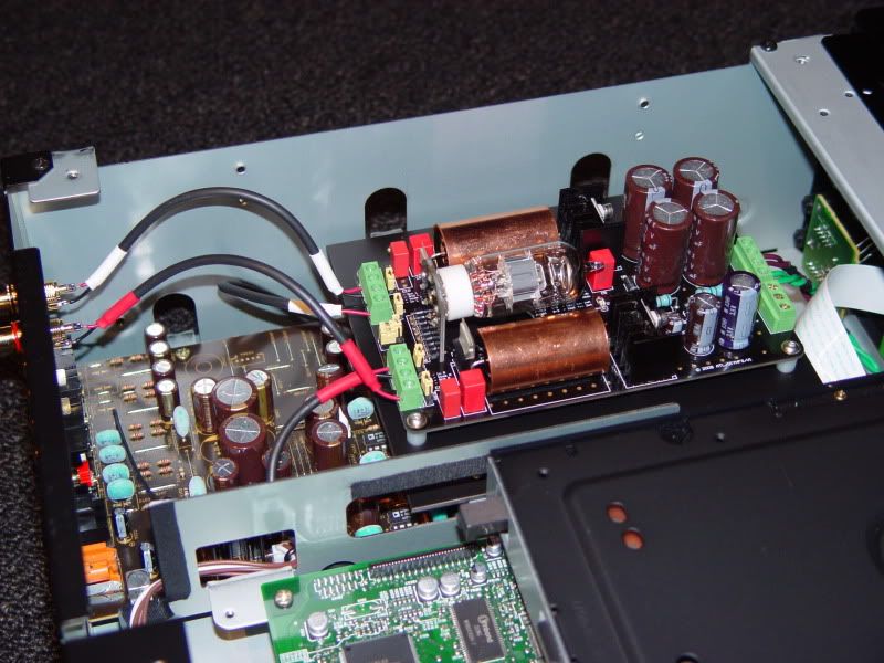
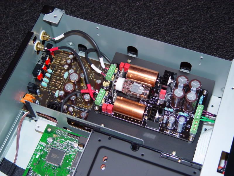
Here are a few photos of the installation:
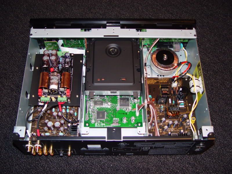
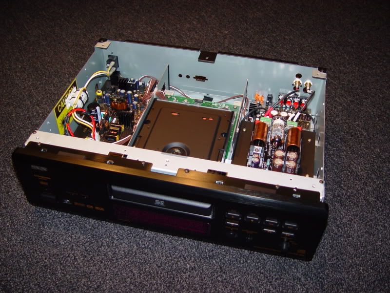
I nestled the power transformer behind the existing power switch, after relocating a few circuit boards.
The transformer was fastened to the chassis with one 6MM bolt thru the bottom.
To fit the tube output board, I had to remove the video portion of the player. This was not a problem
for me as I use the unit for CD playback only. An aluminum plate was fabricated to mount to (4) newly
vacant mounting tabs....in turn, the board was bolted to that plate.
The output signals were taken to a pair of chassis mounted RCA jacks installed into some unused holes.
The sound is very good! Smooth, extended frequency response, and very musical....MUCH better than stock!
Thanks for all the help Brian,
Mike
- RE: UPDATE! - The 'Universal Tube Output Stage' has been installed.... - Thorsten 08:41:15 01/19/10
(0)
- In Reply to: RE: UPDATE! - The 'Universal Tube Output Stage' has been installed.... posted by Mikey on January 18, 2010 at 08:50:05
Hi Mike,
Would you mind sending me an e-mail through the forum system, I'd like to ask you something in private?
Ciao T
- RE: UPDATE! - The 'Universal Tube Output Stage' has been installed.... - bcherry 01:47:49 01/19/10
(2)
- In Reply to: RE: UPDATE! - The 'Universal Tube Output Stage' has been installed.... posted by Mikey on January 18, 2010 at 08:50:05
Thanks Mike for taking the time to post that and your listening impressions. The word is finally get out that real tube anode output as opposed to a tube buffer delivers the music.
worst: opamps
better: tube buffer
best: tube output stage
regards
Brian
DIY - Done Right!
- RE: UPDATE! - The 'Universal Tube Output Stage' has been installed.... - Gnnett 21:53:58 01/23/10
(1)
- In Reply to: RE: UPDATE! - The 'Universal Tube Output Stage' has been installed.... posted by bcherry on January 19, 2010 at 01:47:49
Brian
Where does passive IV conversion with transformer fit into this list?
Regards
Grantn
- RE: UPDATE! - The 'Universal Tube Output Stage' has been installed.... - bcherry 21:56:25 01/24/10
(0)
- In Reply to: RE: UPDATE! - The 'Universal Tube Output Stage' has been installed.... posted by Gnnett on January 23, 2010 at 21:53:58
We haven't done any A/B comparisons as difficult to implement. But I would expect it to sound very good if done right.
regards
Brian
DIY - Done Right!
- RE: UPDATE! - The 'Universal Tube Output Stage' has been installed.... - bcherry 21:56:25 01/24/10
(0)
- RE: UPDATE! - The 'Universal Tube Output Stage' has been installed.... - Gnnett 21:53:58 01/23/10
(1)
- RE: UPDATE! - The 'Universal Tube Output Stage' has been installed.... - Thorsten 08:41:15 01/19/10
(0)
- UPDATE! - The 'Universal Tube Output Stage' has been installed.... - Mikey 08:50:05 01/18/10
(4)
- RE: Thanks Brian! I found a perfect spot... - bcherry 04:53:53 01/05/10
(5)
- Thanks Brian! I found a perfect spot... - Mikey 08:29:45 01/04/10
(6)
- RE: DAC Output Stage - order placed! - bcherry 16:53:41 01/02/10
(7)
- DAC Output Stage - order placed! - Mikey 08:13:26 12/31/09
(8)
- RE: DAC Output Stage - a few more questions.... - bcherry 21:17:09 12/30/09
(9)
- RE: DAC Output Stage - a few more questions.... - Mikey 16:54:44 12/30/09
(10)


Post a Followup:
| FAQ |
Post a Message! |
Forgot Password? |
|
||||||||||||||
|
||||||||||||||
-
To view your new posting or follow-up, click on the RELOAD or REFRESH button on your browser.
This post is made possible by the generous support of people like you and our sponsors:

[
[ General ] [ Speakers ] [ Tubes ] [ Vinyl ] [ Digital ] [ Hi-Rez ] [ Video Asylum ] [ Cables ] [ Tweaks/DIY ] [ Music ] [ Films ]