 |
Audio Asylum Thread Printer Get a view of an entire thread on one page |
For Sale Ads |
|
|
Audio Asylum Thread Printer Get a view of an entire thread on one page |
For Sale Ads |
71.39.40.4
In Reply to: when horn expansion and mouth size exceed the 1/4 lambda posted by Artemius on January 24, 2007 at 13:48:16:
The requirement of a horn pathway length being 1/4 wavelength is rather a waste of time. More of an "old" rule of thumb.The actual horn pathway length is determined by the throat size, the flare rate, and the mouth size, where the mouth size is a relative constant. A general accepted "rule" on mouth size is that mouth circumference = 1/3 wavelength. This is the "relative constant" part, if you want a reasonable match to the environment, and that is then dependent on the radiation angle that the horn exhausts into.
Since the requirements of the mouth size are relatively "fixed", that leaves the flare rate (Fc) of the horn, and the throat size as variables. Altering either or both of those will automatically have an effect on the horn pathway length. Throat size is a matter of efficiency, desired SPL, and band width. Limiting that to an excessively small size (as demanded by the 1/4 wavelength "rule") is limiting the potential of the design.
See why you can't just apply the 1/4 wavelength "rule" out of hand - it has no real meaning... we all know that MOST horns are quite a bit shorter than 1/4 wavelength at Fc and still perform quite well. In general, a very short horn path would, in theory, require fairly accurate annulling to make the driver in question fairly insensitive to variances in reactance.
DM

Follow Ups:
HiActually, if your talking about raising the efficiency of a driver, it does matter how long it is. The quarter wavelength mode is considered the lowest usable F or frequency below which the radiation returns to that of a sealed box direct radiator.
So far as efficiency, a horn isn�t actually efficient until it is 1 / 2 wl or longer as the efficient mode requires the driver be at an excursion maximum.
Best,Tom Danley

Not going to buy that one (by itself), Tom. That implies that for every possible radiation angle and every Fc for a given horn, there is also an optimum specific throat size, and that simply is not the case, because that depends on the characteristics of the driver.The throat size of the horn dictates the characteristics of the response, such as overall efficiency, distortion, and band width.
That also misses the fact that its operating under increased acoustic impedance that defines the efficiency of a specific driver in a specific horn within the available characteristics of the driver and the "available" throat size.
Presumably, you are using the horn pathway length (and the resulting smaller throat size for a given Fc) as a means to increase the acoustic resistance "seen" by the driver. However, it leaves out the driver from consideration, which in turn, directly effects the throat size appropriate to the application.
There are also other ways to achieve the same goal of increased acoustic impedance without increasing horn length.
DM

HiRadiation angle does not enter to it at these dimensions; angular coverage is set where the mouth is larger than needed for impedance transformation. Directivity can raise the on axis SPL but not efficiency.
I would describe the situation more like this:
The expansion rate governs how low the horn can transform impedance, a 30 hz horn needs to double its area about every two feet, a 60Hz horn, every foot.
Horns are fundamentally resonant devices, the lowest mode a horn can resonate is its quarter wave mode, it can�t reach maximum efficiency until it is at least one half WL long.
For every driver and desired high and low cutoff, there is an appropriate rear volume, front volume, expansion rate and mouth diameter.
Conversely, if one wants a high efficiency horn with the physical properties defined, then the driver properties can be found.
The math which defines this stuff (like Marshal Leach�s and Don Keele�s) all assumes one is on the flat part of the horn radiation curve.I am game, how does one increase radiation resistance without adding length?
Best,Tom

"I am game, how does one increase radiation resistance without adding length?"
By reducing the flare rate, which can result in an increase in overall sensitivity. But if not accompanied by an increase in path length and mouth area fc won't be lowered, so in and of itself increasing radiation resistance won't necessarily get you where you want to go.

Bill is right. You can also undersize the horn cavity opening slightly without altering the (larger) throat cross-section. This has a limit, of course, where it will start to act as a low-pass filter.Additionally, you can add one or more drivers in the same cross-section.
You can use multiple flare-rates on the horn itself, and alter the acoustic resistance (or a better word is "control") that way. Olson pointed out that using multiple flare rates can present any desired impedance to the driver.
DM

Ahh.. but for a horn, in order to have the driver �feel� the radiation resistance at the mouth, the rate of expansion is set by the low cutoff.
For example a conical horn with a given mouth dimension will have less low end loading than an exponential horn with the same mouth dimension and length.
The driver in the conical horn is sort of isolated from the mouth because of a rapid initial expansion not coupling thru where the expo has a constant expansion rate (doubles every X distance).
Best,Tom

Don't forget that we are talking bandwidth, efficiency, and acceptable distortion levels here. In the case of a single flare-rate horn, the maximums of all of the above are determined by the horn proportions and in particular, the throat.Multiple flare-rates will allow for a wider bandwidth and lower distortion, and maximum efficiency across the bandwidth if properly used as compared to a fixed single flare-rate horn for the same resultant Fc.
A conical horn will be much longer for a given Fc when compared to an exponential flare because it does not double its cross-section in equal distances like an exponential expansion.
DM

Hard to disagree with an ex hippie now dedicated acoustic scientist
armed with a tek analyser!!!! So bottom line set horn expansion rate based on LF needs...this determines mouth size and length of horn. Throat area is determined by above and specific driver involved (and where you "tap imto horn") And lets not get into tapped horn specifics but certainly efficiency is up there with 50% in four TH115 cabs!!! Speaking well for need for 1/2 wavelegth length for efficiency even if in tapped configuration.

"For example a conical horn with a given mouth dimension will have less low end loading than an exponential horn with the same mouth dimension and length".
Of course, because of the flare rate of the conic versus the exponential. While the exponential flare near the mouth is rapid that's not where most of the resistive characteristic of the horn is derived; that happens at the throat, where the horn cross section is the smallest. The quicker the expansion near the throat the less the resistive loading. And, more to the point of the question at hand, vis-versa.

The bottom line is that overall horn pathway length has nothing to do with efficiency. It has to do with variances in reactance "seen" by the driver.Efficiency is determined by the throat and driver combination, and the acoustic resistance best suited to the driver as defined by the throat size and proportion, along with the conditions that the horn itself defines, such as flare rate, cross-section and mouth size, as defined as acoustic resistance seen at the throat by the driver.
A properly annulled driver is relatively insensitive to variances in reactance (the expected result of a "short" horn with a properly sized mouth), so the so-called requirement of horn pathway length is lessened to the point of being a non-issue.
The overall horn pathway length is whatever it works out to being defined by the throat size and the mouth size. Essentially, the pathway length is whatever is needed to get from point A to point B while maintaining the appropriate expansion rate(s).
DM

"The overall horn pathway length is whatever it works out to being defined by the throat size and the mouth size. Essentially, the pathway length is whatever is needed to get from point A to point B while maintaining the appropriate expansion rate(s)."
True, if you're building a 'perfect' horn, which, practically speaking, usually means an fc of 100 Hz or higher. Going lower space considerations more often than not make compromises a necessity. In that case I've found that path length trumps flare and mouth area in terms of getting the lowest extension possible from a box of finite size. At the expense, of course, of broadband sensitivity and ripple free response.

For a single flare, small throat horn - more than likely a good recommendation, I know its been around since the early 1900's.A pathway length of 1/4 wavelength of Fc is recommended for smooth response (less reactance variation caused by reflections from the mouth) in such a case. But it doesn't have anything to do with overall efficiency! That is determined by the throat.
Since the two (pathway length and throat size) are inextricably related, I suppose that is the crux of our problem.
I just want to point out, having a certain length pathway is not a requirement for good horn performance nor is it a guarantee that you will get the performance you intended.
DM

The devil is in the details. Some generalizations are possible but sure as you generalize something an exception ruins your view.

Well, this is a forum, and we're not writing a damn book!
People should take this info and look it up for themselves for deeper meaning and further details and explanations.
Anyone looking for details should not be trying to get them from a forum anyway.I'm only concerned with whether the info I have posted is correct for the context it is in, and references can be found to support it.
What EXACTLY do you expect? A novel?
DM

I agree. When you look things up, you'll find very few generalizations are accurate enough to be useful. Take for example, the generalization that horns add some arbitrary impedance, like 2 ohms or 4 ohms. The truth is that horns are resonant devices and are highly reactive, especially basshorns. That means there are peaks in impedance spaced in between with broad regions where no impedance rise is seen. Another example of an inaccurate generalization is the one that says mouth size sets efficiency. If one were to generalize, it would be more accurate to say it sets an efficiency/bandwidth product, like Hoffman's Iron Law. Mouth size, efficiency, bandwidth, pick any two. Even that is an over generalization, and one must consider other factors (like driver, front and rear chamber and especially environment) to understand the horn system.

Horns specifically DO add acoustic impedance to the driver, and that is seen GENERALLY electrically by the driver as an increase in electrical impedance or the overall "Z" for the driver in the particular horn. Remember that a driver is also a microphone and has an influence on the electrical signal, that is, it is not just a one-way ticket, electrically. This is seemingly further mythologied in that PWK said in print that the Khorn 4 Ohm driver becomes the equivalent of 16 Ohms when placed in the horn. Was he talking acoustically, maybe, but there is no electrical evidence that an overall Z of 16 Ohms is actually the case, so what he was intending to clarify is still up in the air. It however can be assumed that PWK generally knew what he was talking about. But there is a change of overall Z for the driver when actually in the horn. And that CHANGE would apply across the board to ALL horns... but there is no fixed value that can be assumed in the general sense concerning the change in overall "Z" that can be implied, of course. The generalization is that there will be a change to the overall Z when the driver is in the horn.Mouth size determines efficiency? Never heard that one, and it's certainly not true.
Throat size determines efficiency. Now that's certainly true. Check Keele's "Low Frequency Horn Design Using Thiele/Small Driver Parameters", AES preprint 1250, May 1977.
DM

I also beg to differ on the above where you said a horn is a resonant device - it is not. The DRIVER is a resonant device.Specifically a horn is a frequency-range SPECIFIC device, but it is NOT supposed to display any resonant response characteristics - that is a sign of a malformed horn!
The horn itself is NOT to suffer from resonances (that is a construction problem).Well designed horns do not resonate. Resonance is indicative of a loss of acoustic energy.
DM

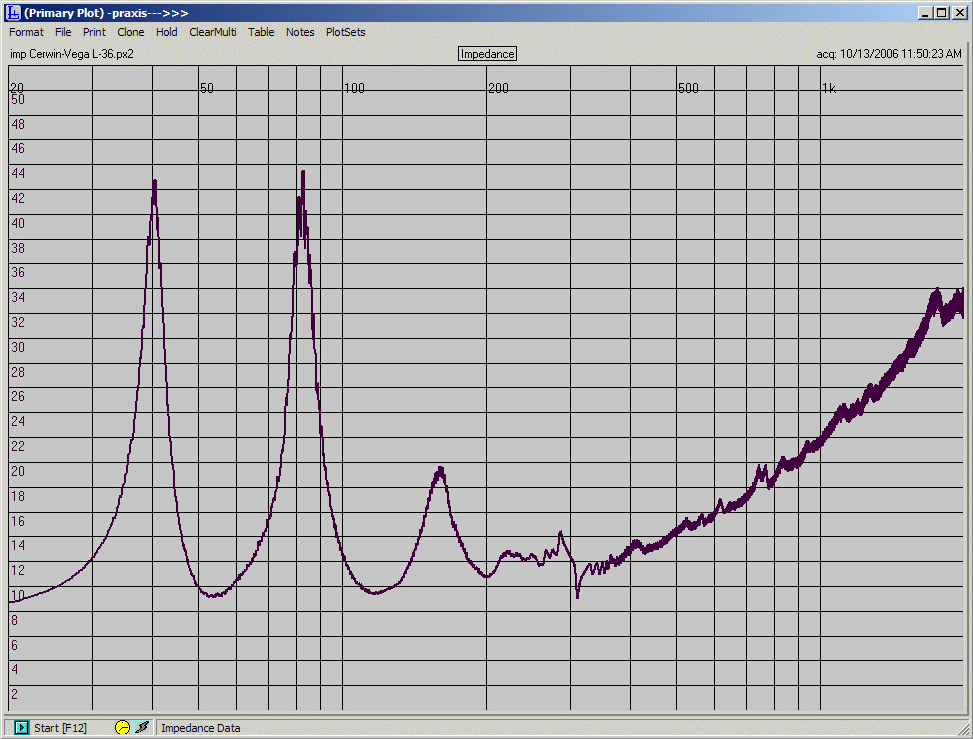
This is the measured impedance curve of a popular basshorn. The characteristic peaked impedance curve is typical of all basshorns. Notice the DC impedance value at the left. Compare it with the impedance value between peaks. This impedance curve looks very much like a tuned pipe. There is an impedance increase, but it isn't a fixed resistive increase.

Greets!True, measurements of a typical bass-horn show them for what they are, basically big tapered vent reflexes to keep their size as compact as practical. A reactance annulled bass-horn though is an all-together different 'animal' with a nominally flat acoustic and electrical impedance in its passband. Unfortunately, it's also too big for most apps, with an Fc <10 Hz for a BLH using a typical midbass horn driver.
GM

I know of no basshorn that exhibits a flat impedance curve. Can you point one out?

Greets!Like I said, it would be far too big with typical drivers, so no, I don't know of one. You can prove its validity though by using a high Fs, relatively high Q driver to keep it a reasonable size though. I don't understand why you question this since you pretty much explained the 'why' in your response here: http://www.audioasylum.com/forums/hug/messages/118571.html
".........but it does show that the horn becomes more resistive at a frequency where its size is large compared to the wavelengths presented to it, nearing the top of the passband."
IOW if you tune it with a large enough horn with its center frequency of SQRT(Fl, Fh) = Fs, then the horn will completely damp it, just as Plach noted and as Thuras, Olson and others understood early on judging by their compression driven horn designs.
GM

I wasn't questioning "why" one would want a resistive load, but making a (rhetorical) question about finding a basshorn that didn't have pretty significant swings in reactance and impedance peaks as a consequence. The reason was to illustrate the fact that basshorns are generally pretty small compared to wavelength, and they exhibit transmission line behavior as a result. Reactance annulling cannot help this, as it can only counteract one standing wave node.

From Plach "Design Factors in Horn Type Loudspeakers", JAES...."The mechanical impedance of a driver is resistive only at its resonant frequency and is highly reactive at any other frequency. If the cutoff frequency of the horn is placed below the unloaded resonance of a driver, the horn reactance is positive and increasing with decreasing frequency while the driver reactance is negative and also increasing with decreasing frequency.
Thus it is possible to make the net mechanical reactance between the horn cutoff and driver resonance close to zero.
The [horn] cutoff frequency is generally chosen as the point where the net mechanical resistance is zero, since in the finite horn the mechanical resistance at and below cutoff is not zero but has a finite value which is a small fraction of the asymptotic value.
This expedient leads to a large efficiency improvement at and near cutoff."
He goes on to say that an annulled driver (i.e., the "consumate match" as described above) is "relatively insensitive to large variations in reactance".
Hence, short horns displaying large variations in reactance resulting from reflections from the mouth can perform quite well when an annulled driver is employed.
That's all I want to type, so there it is...
DM

Look at the impedance curve of any basshorn. You'll find out that it is highly reactive through most of its range. They become more resistive but only above the range they are designed to be used in. This is a result of their size.

The question being 'does a horn add to the nominal driver impedance' the answer is yes. Does it add a set value to impedance at every frequency? No. Does a particular horn add to what's really of concern to the end user, the minimum load shown to the amplifier? Yes.

The point I've made is that it is inaccurate to say a basshorn adds a fixed value, say 2 or 4 ohms, to the impedance of the driver. To instruct people otherwise misleads them, because it fosters a basic misconception about how horns work.

I agree with that statement - that's not the issue I'm talking about.Electrical impedance (Z) of the driver in the horn is not indicative of the overall frequency response of the horn, and to imply that it does is false.
DM

Frequency response is another issue entirely. A speaker at resonance is resistive, and that indicates something about how it will behave. It may have flat response through that range, or it may not.Back to the subject of impedance, one finds that it is higher at resonance. The impedance peaks of a basshorn indicate standing wave resonant behavior, much like a quarter wave pipe. The fact that there are several peaks shows that the device has large swings in its reactive phase angle. It is only resistive at the impedance peaks, and at relatively high frequency where the horn becomes resistive over a wider band.
In the example shown earlier, the horn becomes reasonably unifomly resistive above about 200Hz. That's higher frequency than the basshorn is likely used, but it does show that the horn becomes more resistive at a frequency where its size is large compared to the wavelengths presented to it, nearing the top of the passband.

Indeed. I just didn't want anyone to get confused as it shows frequency (of course).However, where this all toes the accepted theory line, how does one explain the performance of the Klipsch Jubilee (in particular) which has a remarkably wide USABLE bandwidth AND high efficiency AND small size (relatively speaking) for a 38Hz Fc bass horn? It is literally remarkable, and what - nobody here knows about it or they choose to ignore it as a matter of convienience?
It is nothing remarkable in the design, per se, we all know what combinations it employs. It is just well-founded horn design with a really outstanding response due to the choices that were made! For its intended purpose and market niche it is going to be hard to beat.
That's why I don't buy all this at face value, although everything said is technically true, but the implied limitations are not QUITE true - if what is being said about the limitations is true, then what about the Jubilee? Don't get me wrong, I'm definitely NOT a fan of 12" drivers... but the level of performance is nothing to scoff at, and that is a bonifide fact. Kiss goodbye to the 3-octave rule for bass horns, it's dead and gone, my friends.
DM

I think we might be talking about two slightly different things here. A pure horn, or at least what I and some others might define as a "pure horn", is one that has a basic flare driven by a diaphragm. It's a simple device, with characteristics determined by its properties. One of those characteritics is bandwidth, another is impedance, another still is efficiency, and so on.There are other acoustic devices besides horns that can be employed to modify the horn's characteristics somewhat. Resonators (be they Helmholtz chambers or standing wave reflectors) can be employed to cancel modes formed by the main horn. The rear chamber can be tuned in a similar fashion. Likewise, electrical devices can also be employed, things like notch filters, compensation networks, and so on. These acoustic and electrical filters can be used to extend bandwidth, reduce impedance peaks and smooth response.

Not to me, I've been talking about the same thing all along; short horns can be designed that do not display reactance problems, however, I previously agreed that the general 1/4 wavelength long pathway "rule" was appropriate for single flare-rate horns.Is that why you guys have been arguing with me? I was beginning to wonder what that was all about...
My opinion is single-flare rate bass horns cannot compete with multi-flare ones on a performance level (and all that entails) given the constraints of footprint size, bandwidth, nominal Fc, and overall cabinet volume.
DM

Well, no, I'm not talking about flare rate. I'm talking about additional devices, such as Helmholtz resonators, standing wave reflectors, etc. When those things are incorporated, they change the landscape a bit. One cannot make an undersized horn without associated impedance peaks, but by adding additional devices, one can counter the impedance peaks. It's the added resonators that do the trick.

But I'm not necessarily talking about "undersized" horns, actually SHORT PATHWAY horns, in particular BUT I should add that I'm refering to1/8th space horns, too, as in the case of the Jubilee. Correct mouth size for the Fc, large throat area = short pathway, well under 1/4 Fc wavelength down to around a meter in length.In such a case, annulled drivers and multiple flare rates can get you where you want to go, and in a wideband manner, too.
We've all seen Olson's seminal work regarding foreshortened horns in "Acoustic Engineering", etc., I'd point out that he noted that changing the throat size had much less effect than changing the mouth size, for instance, on the overall reactance. But then those examples were single flare-rate horns and were not annulled considering the "new" larger throat size (changes as a lessening of acoustic resistance), either, which would likely have an potentially exploitable effect.
DM

But i'm not entirely convinced klipsch's stuff can be classified as a horn. Multiple flare rate seems to be a gross understatement and the mouth on the lf section of the jubilee sure seems to bear that out. The lascala, is even weirder.

If Sd exceeds throat area and mouth area exceeds throat area it is a horn. How far down it operates in horn mode is another question, but PK answered that one as well.

Horns specifically DO add acoustic impedance to the driver, and that is seen GENERALLY electrically by the driver as an increase in electrical impedance. Remember that a driver is also a microphone and has an influence on the electrical signal, that is, it is not just a one-way ticket, electrically. In most cases, the differences are rather slight. This is seemingly further mythologied in that PWK said in print that the Khorn 4 Ohm driver becomes the equivalent of 16 Ohms when placed in the horn. Was he talking acoustically, maybe, but there is no electrical evidence that an overall Z of 16 Ohms is actually the case. But there is a change of overall Z for the driver when actually in the horn. And that CHANGE would apply across the board to ALL horns...Mouth size determines efficiency? Never heard that one, and it's certainly not true.
Throat size determines efficiency. Now that's certainly true. Check Keele's "Low Frequency Horn Design Using Thiele/Small Driver Parameters", AES preprint 1250, May 1977.

Wow, I guess I can just repost the same crap over and over as much as I want? Sort of like being a Democrat, ain't it?! I'll just keep reposting it until it becomes true!Lookout! I've got an itchy mouse-button finger!
DM

Hi Tomhere's a bouple of midbass
Best,
FreddyFH1 - 30 inch path

System 100 Edgarhorn midbass ~21 inch path


Well, I messed that one up. Here's the conventions on horn mouth size:Diameter = 1/3 wavelength (Kellogg) [Augspurger said 1/4 wavelength]
Circumference = wavelength (Keele)
DM

This post is made possible by the generous support of people like you and our sponsors: