MagneQuest/Peerless Forum

Welcome! Need support, you got it. Or share your ideas and experiences.

Return to MagneQuest/Peerless Forum


Message Sort: Post Order or Asylum Reverse Threaded

TFA-204 300B Operating Points

129.244.12.109

Posted on March 7, 2017 at 12:34:03
jdrouin
Audiophile

Posts: 28
Location: Oklahoma
Joined: July 14, 2015


So, I'd like to breadboard a 6SN7 --> 300B SET circuit using Magnequest TFA-204 OPTs. It's a fairly well documented combination, but let me be up front that I'm trying to regain the sound of a pair of George Wright mono blocks I heard years ago, that have stuck in my memory ever since. This might be a sensitive topic given that some of you knew him well, so please let me know if it's inappropriate and I'll delete the thread.

Given that the TFA-204 is spec'd for 3K and 60mA, the operating points for the 300B would need to be pretty conservative. The usual idle current at 70% OPT maximum current capacity would be 42mA, falling in the range of the following from the WE 300B datasheet:

300V plate, 50mA, -63V grid into 3K for about 6w output
250V plate, 40mA, -52V grid into 3K for about 4w output

I've also seen some 300B SET builders (i.e. for the Fi Primer 300B) who liked:

310V plate, 42mA, -60V grid into 3K

The circuit I want to breadboard was a one-off that George was playing with when he sold them to my friend ca. 2000-2001: a WPA 3.5/Mono 8 (same topology) using a 300B and the TFA-204. I figured I'd start with a revers-engineered schematic posted by a WPA 3.5 owner at diyaudio (attached, accuracy uncorroborated), adjusting the voltages for 300B operation.

Do the above parameters seem viable for the attached circuit? Should I go closer to 350V/60mA -- even though it's already at max current?

Mike, if you're reading this, do you happen to remember the amp in question and its operating points?

If anyone knows of a more accurate schematic, or of how George's thinking would have suggested the op points, I'd really appreciate it.

Many thanks,

Jeff


Hide full thread outline!
    ...
RE: TFA-204 300B Operating Points, posted on March 7, 2017 at 14:58:29
triode3
Manufacturer

Posts: 357
Location: Midwest
Joined: August 23, 2005
That choke in the ground of the power supply has to be an error, particularly because you show a voltage drop (12VDC) between the two filter capacitors. It must go in between the 22uf and 100uf on the high voltage side, not the ground side.

Personally, you use the 22uf as you don't want to reach the maximum capacitor input to filter rating of the 5Y3GT, then you charge up a 100uf behind it, using the choke as a current limiter (but in reality, you are using it as a pi filter to get lower ripple). Why would you do this? Just put a 5AR4 in there and increase the first filter cap. You are going to have much lower ripple after that. OR just do 22uf->choke->22uf->choke->22uf+plate. (a-la Bugle amplifier if I recall).

Consider, if you hit a HUGE passage in music, the 5Y3GT still has to charge up the 100uf, through the choke. You could run out of power... why go there? Either put more filtering in, or get a tube that can supply more current to charge up your reserves. My $0.02.

If I am on my high horse, those 480ohm balancing resistors in the 5V supply are also being used to drop the voltage according to your schematic. Personally, (and this is totally my $0.02), I would have my transformer winder make the AC voltage going to the plates of the 5Y3GT (ops, 5AR4 in my dream) 11V less, and ditch the resistors. Otherwise, they have to be large, and you will wake up at 2:30am in a cold sweat wondering if those resistors are "good enough" to go in your power supply. :)


RE: TFA-204 300B Operating Points, posted on March 7, 2017 at 16:13:49
jdrouin
Audiophile

Posts: 28
Location: Oklahoma
Joined: July 14, 2015
Thanks, triode3. I will keep these comments in mind, for sure. Right now I'm just interested in reproducing George's design accurately rather than modifying it, even though it uses a lot of unorthodox methods.

For instance, the power supply choke is indeed in the ground leg, according to the owner who derived the schematic (which might not be totally accurate):

http://www.diyaudio.com/forums/tubes-valves/227426-wright-audio-wpa-3-5-humpot-schematics-2.html#post3405178

Kyle K also said this in conversation with Paul Joppa on 02/12/2013:

"On the WPA 3.5 I looked at, the choke was in the ground leg"

which you can land at here:

http://www.meter.com/cgi/t.mpl?f=set&m=72462

There's another thread, I think at the Bottlehead forum, which describes the choke in the negative leg as "an old school trick" that George used.

I've looked at a tone of gut shots of the WPA 3.5 and the Mono 8, and the components seem to conform to the values expressed in that owner's schematic -- and even more interesting, is that they're the same for the WPA 3.5 and the Mono 8, even though the Mono 8 ran 300Bs with the FS-030 at presumably a higher voltage and current rating than the one-off I heard that used the TFA-204.

I'm learning LTSpice right now in order to model the schematic and come up with some values. It's coming along, but I've not had luck modeling the power supply on this or the Fi Primer 300B, which is a little more straightforward.


RE: TFA-204 300B Operating Points, posted on March 9, 2017 at 14:33:19
mqracing
Manufacturer

Posts: 4323
Joined: June 29, 2000
The dc plate current rating on the TFA-204 is conservative and can run at 60 mils all day long without breaking a sweat. All the while preserving adequate AC (the musical signal) headroom.

The operating points you posted but appear to be wary of... actually don't look all that bad (at all I might add).

re: power rating. the difference between four watts, six watts, or eight watts output translates into very little difference in loudness in terms of driving a speaker. It's most likely that any speaker that is not happy with four watts output will be equally unhappy with eight watts driving it.

Also bear in mind that a set of operating points with reduced idle current
can be optimized by regapping (with a smaller gap) the output trans and hence gaining valuable primary L.

Remember your "real" impedance is the product of the primary L in parallel with the reflected load impedance from the secondary.

Re: recollection of George's operating points for the amp in question I do not have that data.

MSL


Builder of MagneQuest & Peerless transformers since 1989


RE: TFA-204 300B Operating Points, posted on March 9, 2017 at 18:50:31
jdrouin
Audiophile

Posts: 28
Location: Oklahoma
Joined: July 14, 2015
Thanks, Mike. So, if you're saying a 350V/60mA op point is OK with the TFA-204, then I'll see what I can do with that.

The more I read around, the more it seems George liked to go "by the book," choosing op points from tube datasheets.

For now I'm going to try this with parts I already have, which are a PT with high voltage secondaries of 720V and 660V and a GZ34 rectifier tube. I'll see if I can get working LTSpice models for the combos mentioned in my original post, and then order parts to try them all out.


What's the Turns Ratio of the TFA-204?, posted on March 9, 2017 at 20:10:37
jdrouin
Audiophile

Posts: 28
Location: Oklahoma
Joined: July 14, 2015
I'm trying to model a circuit in LTSpice and the B+ is dropping way too much as it goes through the 3K primary of the TFA-204 to the plate of the 300B. Either I'm using the software incorrectly or 3Kohm might not be the actual value affecting voltage.

A Help Page at DIY Audio Projects says, "To determine the load resistance for the desired given speaker load, square the turns ratio you calculated and multiply that number by the desired speaker load (i.e. 4, 8, 16 ohms)."

Can you tell me the turns ratio of the TFA-204 so I can calculate this?

Thanks,

Jeff


RE: What's the Turns Ratio of the TFA-204?, posted on March 9, 2017 at 20:56:50
mqracing
Manufacturer

Posts: 4323
Joined: June 29, 2000
The turns ratio is the square root of the impedance ratio.

The nominal impedances of the 204 is 3k primary and 16, 9, and 4 ohms.

Therefore the turns ratio from primary to say the 9 ohm secondary tap is 18.26 to 1.

MSL


Builder of MagneQuest & Peerless transformers since 1989


RE: TFA-204 300B Operating Points, posted on March 10, 2017 at 13:39:17
jdrouin
Audiophile

Posts: 28
Location: Oklahoma
Joined: July 14, 2015


I've made a rudimentary model of the circuit in LTSpice, which I'm just starting to learn. This first attempt ignores the power supply from the schematic above, using DC voltage sources to drive the signal section only.

The plate and cathode voltages of the 6SN7s are about 10V below those measured in the schematic. The OPT and 300B are a different story altogether.

According to an LTSpice video tutorial on transformers, you model the shared inductance across the transformer by creating separate inductors for primary and secondary, and connecting them via a K statement, which I've done. You need to set the inductance values to reflect the square of the turns ratio.

I'm not sure if this was the correct way to do it, but since Mike says that the turns ratio of the primary to the 8ohm secondary is 18.26 to 1, if we round down to 18, the square is 324, so the primary and secondary H values (L1 and L2 in the schematic) are set to 324H and 1H.

If I set the B+ supply at 250VDC and enter 3K as the series resistance for the OPT primary, the B+ becomes way too low at 80V.

However, an analysis graph reveals that the current in the OPT primary and the plate of the 300B are acceptable, between 50-60mA.

So, it would appear I need to figure out how to model OPTs better, but it seems like this is getting somewhere. Any pointers appreciated.

Thanks,

Jeff


First Simulation, posted on March 11, 2017 at 14:42:36
jdrouin
Audiophile

Posts: 28
Location: Oklahoma
Joined: July 14, 2015


After doing some more digging, I found a thread here where Mike indicated the DC series resistance of the TFA-204 primary is 140 ohm.

Also, the previous LTSpice schematic contained an error. I though I had to enter the 5VDC voltage source for the 300B filament, but that is assumed by the software. Instead, you treat that as a cathode. So I removed the 5VDC source and added the cathode resistor with bypass capacitor that I had mistakenly left off before.

A member of diyaudio (where I'm also modeling a Fi Primer 300B with the TFA-204) helped me figure out that, since the primary inductance is 10H, and the turns ratio is 18.26, the inductance for the secondary should be 0.03H in the sim: 10/18.26^2 ~ 0.03H.

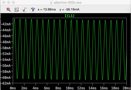
With all of that information entered into the model, and with a hypothetical rectified B+ of 358V after the PS (not modeled yet) and a cathode resistor value of 1.2K, we get 350V on the plate and current that peaks to about -61V. The sine wave of current through the TFA-204 primary goes from about -41mA to -61mA peak-to-peak, which seems close to the 8W option originally posted (350V, 60mA, -74V, into 3K = 8w output).

albertine-300b-graph-02

Does that seem right?

Does the 300B datasheet rating mean -60mA RMS or peak?

I don't know what the grid voltage is right now, and I still have to model the power supply.

Also, if this really results in 8W output, it's pushing up against the maximum of the TFA-204 power rating. Wondering if I should aim for the 300V, -50mA, 6W option.


RE: First Simulation, posted on March 12, 2017 at 12:05:24
jdrouin
Audiophile

Posts: 28
Location: Oklahoma
Joined: July 14, 2015


Learning more as I go along. I decided to set the voltage and frequency at the signal input source to 0 and then adjust the cathode resistor to 1K on the 300B to get an idle current of 60mA (plate voltage is still 350V).

Then I reintroduced a signal of 0.7V @ 1kHz, resulting in a current sine wave that neatly reaches -50mA to -70mA peak-to-peak (shown in graph above), exceeding the TFA-204's 60mA rating by 10mA.

A 1V signal produces -45mA to -75mA peak-to-peak.

Is this workable, or would it cause core saturation in the TFA-204?


RE: TFA-204 300B Operating Points, posted on March 12, 2017 at 21:50:16
sideliner
Audiophile

Posts: 208
Location: NYC
Joined: August 22, 2013
Contributor
  Since:
December 15, 2023
3K is not the series resistance of the primary. 3K is the OPT's primary AC impedance. What you need to input, is the transformer's primary DCR which you can just measure with a DVM. That value should be anywhere from 150 to 300 Ohms as is typical for most transformers. If the primary's DCR is say 200 Ohms, there will be a drop across it of: 200R x 0.06A = 12V. You will be going from 250V down to 238V at the tube's plate.


RE: TFA-204 300B Operating Points, posted on March 12, 2017 at 22:08:26
jdrouin
Audiophile

Posts: 28
Location: Oklahoma
Joined: July 14, 2015
Thanks. I don't have the OPTs yet so I can't measure. I did however find a thread where Mike indicates the DCR for the TFA-204 is 140 ohm. I reposted it somewhere in the nest here, but the link is:

http://www.audioasylum.com/forums/magnequest/messages/4037.html


RE: First Simulation, posted on March 13, 2017 at 16:28:40
Gordon Rankin
Manufacturer

Posts: 2928
Joined: June 9, 2000
Ok,

First off, remember a class a amp operates full with 0Vac input. So yes bias the 300B at 60ma. You don't need to worry about the AC-PP current as that is not an issue. Remember class A 0Vac input is when the tube is running at max power.

Second if you are doing a simulation you need a ton more data. Remember the Rp of the tube effects the results as it is in a sense in parallel to the tube.

Also remember when approaching 60% of the bias voltage in an AC input signal to the 300B that the grid will start to draw DC current which will increase the voltage across the grid resistor and rebias the tube.

You do know that your going to need a boat load more AC voltage input to the 300B. Looks like your gain tube is going to result in like 18Vacrms gain and the 300B is going to need 51.63Vacrms into the 300B to get to 8W's. That means you need about 3Vacrms input to make that work.

Also work in voltage, tubes are voltage devices, working in current is just going to confuse you.

Thanks,
Gordon


J. Gordon Rankin


RE: First Simulation, posted on March 13, 2017 at 18:06:45
jdrouin
Audiophile

Posts: 28
Location: Oklahoma
Joined: July 14, 2015


Thanks, Gordon. Several members at diyaudio helped me figure out that the datasheet numbers for, say, plate voltage actually mean plate-to-cathode. So, the 350V operating point actually requires a B+ supply of 435V, which puts 425V on the plate after passing through the 140 ohm primary of the TFA-204, requiring a 1.25K cathode resistor to maintain a 60mA idle current. This combination also results in ~75V on the cathode: 425V-75V = 350v.

So the attached, revised schematic seems to fit the 350V/60mA into 3K operating slot on the WE datasheet.

I've been simming other circuits too, like the Fi Primer 300B, and have been able to come up with a viable power supply based on the resistance across the 300B and the OPT at those voltages (5.8K on the 300B, 1.25K on the cathode, 140R on the OPT = 7190R for the final resistor in PSUD2). It's been cool to see how the results in PSUD2 match the ones I get in LTSpice.

Can't model the power supply for George's amp in PSUD2, though, because his choke is in the ground leg and the software doesn't offer that option. So I think I'll first breadboard a Fi Primer 300B, since it's a little more straightforward, before attempting George's design.

Now that I have a little experience with modeling this stuff, the mathematics in Morgan Jones' book will make more sense, so I've started reading that too.


RE: First Simulation, posted on April 7, 2017 at 20:38:23
Paul Joppa
Industry Professional

Posts: 7295
Location: Seattle, WA
Joined: April 23, 2001
The 60mA rating is for quiescent current (no signal). The AC instantaneous current will be greater, but still within the spec - that 60mA rating allows plenty of signal AC current before saturation issues.


Page processed in 0.031 seconds.