High Efficiency Speaker Asylum

Need speakers that can rock with just one watt? You found da place.

Return to High Efficiency Speaker Asylum


Message Sort: Post Order or Asylum Reverse Threaded

What do you make of this? (Impedance curves)

81.233.250.186

Posted on March 4, 2017 at 07:44:06
pix
Audiophile

Posts: 411
Location: sweden
Joined: March 18, 2006

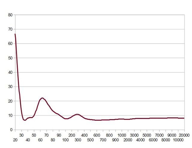
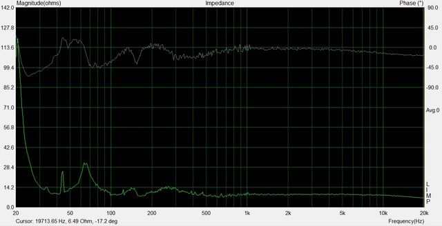
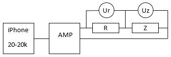
Having tear my hair about having ARTA/LIMP to work with my computer, I decided to make the same setup, but using multimeters instead and making impediance curves in Excel.

By using a calibration resistor I got a deviation curve, which where subtracted from the real measurements. By doing so I think (hope) this is a fairly acurate measurement on my complete speaker setup (measured at the filter input).

So, What could be said about this curve?
Is it good, bad, worth the effort trying to be improved?


Hide full thread outline!
    ...
This was the setup, posted on March 4, 2017 at 07:51:46
pix
Audiophile

Posts: 411
Location: sweden
Joined: March 18, 2006

I simply used a free generator app i my iPhone as a source, using my 300B tube amp driving.
Ur and Uz is multimeters reading AC (rms) voltage
R is a 10,1 Ohm (low inductance) resistor

A second resistor of 10,1 Ohms where used as Z giving a deviation curve used for calibration.


RE: What do you make of this? (Impedance curves), posted on March 4, 2017 at 07:52:06
Bill Fitzmaurice
Industry Professional

Posts: 5370
Location: New England
Joined: October 20, 2002
Something is off. You should not see that rise below 30Hz, and you should see a rise in the highs, assuming there's no zobel in place.


Device under test, posted on March 4, 2017 at 07:58:22
pix
Audiophile

Posts: 411
Location: sweden
Joined: March 18, 2006

The tested speaker filter shown below accept for C5 which where 0,68uF
Drivers where:
Bas: Beyma P15Fe in a Karlsson K-15 cab
Mid: Radian 750Pb (Similar to 850Pb) in a Tricstrax horn
Hi: Fostex T90A


RE: What do you make of this? (Impedance curves), posted on March 4, 2017 at 07:59:55
pix
Audiophile

Posts: 411
Location: sweden
Joined: March 18, 2006
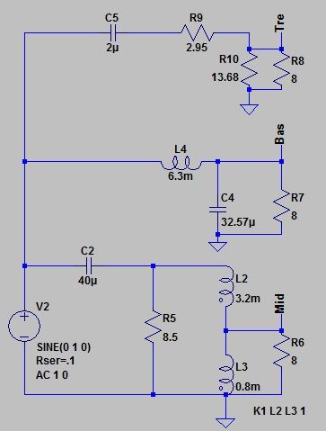
Bill,
No zobel is used


Could it be a matter of limitations of the multi meters?, posted on March 4, 2017 at 12:08:52
pix
Audiophile

Posts: 411
Location: sweden
Joined: March 18, 2006
I am using FLUKE 179 and FLUKE 75III for these measurements.
I am not sure what their accuracy is at frequency extremes?


RE: What do you make of this? (Impedance curves), posted on March 4, 2017 at 14:48:25
freddyi
Audiophile

Posts: 3852
Joined: December 6, 2001
the cabinet type and woofer/subwoofer characteristics need to be stated. the rise at 20Hz could be the lower impedance peak of a large vented cabinet with low Fs woofer tuned a bit "high" (~32Hz) - if so, Z should drop towards Re as it goes down below 20Hz.

A 10 ohm resistor could be compared with the meter at each frequency of interest to correct any non linearity in the meter and allow even cheap meters to work. Just adjust so it reads "10" with the resistor in place, then measure the speaker. Something is flattening or appearing to flatten out the impedance. It takes a function meter or sine generator with fine increments to do it by "hand".
Karlson Evangelist


RE: Device under test, posted on March 4, 2017 at 15:29:38
freddyi
Audiophile

Posts: 3852
Joined: December 6, 2001
all of my good K15 Z plots are gone from the internet - I\ll have to look and see if some still exist. Here's some early ones using Speaker Workshop - looks like there could have been some noise. K15 is tuned in the high 40's


Karlson Evangelist


Woofer characteristics, posted on March 5, 2017 at 23:20:35
pix
Audiophile

Posts: 411
Location: sweden
Joined: March 18, 2006
Thanks Freddyi,
I appreciate that you share your kwnoledge. I am a newbee in this measure topic, and I am trying to learn ;o)

Linked are the woofer characteristics (Beyma P1580Fe). The cabinette is a Karlson K-15, built by the original drawings (including the very low amount of damping material inside the cab). The slot dimensions are according to the drawings. Note that the filter includes a handwired aircored 4mH autoformer (Taped to lower the mid horns 11dB), which may influsence the Zin a bit.

This measure is done at the complete speaker through the filter input (Karlson K-15/Beyma 15P18Fe, 200Hz Horn/Radian 750Pb, Fostex tweeter).
Also, worth mention is that my 300B SE tube amp used for this measure (not sure if this is influencing the measures).

I have the speakers at my countryhouse and will not be able to measure them further untill next weekend. My plan is to measure from DC and up, to see if the 20Hz rise is a peak or not.


BR


RE: What do you make of this? , posted on March 7, 2017 at 05:43:32


RE: What do you make of this? (Impedance curves), posted on March 13, 2017 at 17:25:00
Mr_Steady
Audiophile

Posts: 2042
Location: North Florida
Joined: August 19, 2014


Sorry Pix, the only thing I can offer you is the easy way out. The graphs are for the ALK Universal crossover. It is a first order for woofer/mid and second order for mid/tweeter, and it's right at the points you want.

There was a lot of talk recently on the Tube diy forum about phase shift, and phase shift in crossovers. You can see from the middle graph that there is no appreciable phase shift with this three way crossover. Also the impedance stays within a six to eight ohm tolerance.

What I'm trying to say is these crossovers are designed right. You could pull your hair out trying to design one as good, or you could just spend the $320US. It's too bad but Mr. K used to publish his schematics, BOM, and layouts of his crossovers for diy'ers, but one guy started to build them for commercial gain, so he took them down. That really hurt guys like you.

The autoformer on it will attenuate down 18db, so it will work for you. He also has second order and 120db brickwall filters.

Thinking about it, your woofer goes so high. With a first order slope your woofer is going to be putting out significant signal at 4000Hz. Maybe 10db down before it's rolloff? At some point I think you should try a steep filter on your woofer. Probably asymmetrical like 24/12, or 48/12. Even 24/24. An electronic crossover would make it much easier, and try a nice analog active crossover like the Marchand. I think you will be playing at this for awhile. :)

-----------------------------------------------------------------


Big speakers and little amps blew my mind!


Not quite here yet, bu at least I got ARTA/Limp up and running, posted on March 15, 2017 at 10:23:08
pix
Audiophile

Posts: 411
Location: sweden
Joined: March 18, 2006

Well, going my own way is like an challange for me.
To see what I can accomplish myself with my own ideas.
Today, at least I got ARTA/Limp up and working.
Here are the shart from that measure.


RE: Not quite here yet, bu at least I got ARTA/Limp up and running, posted on March 16, 2017 at 05:43:55
Mr_Steady
Audiophile

Posts: 2042
Location: North Florida
Joined: August 19, 2014
Go for it.

At least now you have a mark to aim for, and maybe a fallback position.


-----------------------------------------------------------
Big speakers and little amps blew my mind!


RE: Not quite here yet, bu at least I got ARTA/Limp up and running, posted on March 16, 2017 at 06:45:36
pix
Audiophile

Posts: 411
Location: sweden
Joined: March 18, 2006
From wthat I have seen on the web, these curves isīnt so bad.
Especially from mid and up ;o)

Actually it is the low freqences that concerns me.

But are those peaks only adjustable electrically, or is there ways to correct them acoustically?

I know that my bass woofer has a slightly wrong Vas for the Karlsson K-15 cab, And I plan to open it upp to add more wool inside.
Could those abnormalies indicate that the BR-port to be increased/decreased while I am at it?


RE: Not quite here yet, bu at least I got ARTA/Limp up and running, posted on March 16, 2017 at 09:09:33
Mr_Steady
Audiophile

Posts: 2042
Location: North Florida
Joined: August 19, 2014
So your graph is an acoustic measurement of your speaker for impedance and phase? I thought is was an electrical measurement of your dividing network.

It may not look bad, but it doesn't look that good either. I suggest you search online for the impedance plot of the Klipsch AA network. I think it will look a lot like yours. The impedance spike down low is what screws up the bass output from a SET amp. That peak is what you want to get rid of. I think you will have to fix it in the electrical realm before you start to try to tweak it in the acoustical realm. Maybe you should take some electrical measurements of your network with a resistor in place of the woofer.

Sorry Pix I am not an expert, and I can't answer any of your questions about bass enclosures, drivers, and ports. There are a lot of people on this forum who know much more about that than me. Hopefully they will chime in. I do know enough to recognize that your woofer is putting out significant sound a decade past your crossover point which can't be good.

I see you accept emails. I may have the schematics for the crossover I showed you on an old computer. I may be able to retrieve them, and may be able to forward them to you if maybe you were interested in them, and maybe if you agreed not to share them with anybody else. That's a lot of maybes, so I'm not making any guarantees. Let me know if your interested.


------------------------------------------------------------------
Big speakers and little amps blew my mind!


Purelly electrical, posted on March 16, 2017 at 14:10:45
pix
Audiophile

Posts: 411
Location: sweden
Joined: March 18, 2006
The measurements is purelly electrical.
The initial one where made manually with a signal generator, a reference resistor and two DVMs. The second, where made with ARTA/LIMP with my computer/soundcard. The similarity then between, strengthen the fact that the measurement where correctly done.

I am a novice in this measure acivities, and not qualified to state what causing that hugh 20Hz peak. My thought where that the cabinette could generate some sort of woofer resonance generating back EMF?
I will try replacing the woofer with an 8 ohm resistor to see what happend.

Those filter schematics would be very much appreciated :o)


New measurements , posted on March 17, 2017 at 05:32:28
pix
Audiophile

Posts: 411
Location: sweden
Joined: March 18, 2006


I am not sure how to link to several pictures in one post, so I add three separate posts.

First, I have measured the impediance of the complete speaker ones again. But this time from 10Hz upp to 20k.
This was just to make sure that the rising impedans low end cuve actually was a hugh peak. And it was.

Actually, I donīt see this 21Hz peak as a problem, since the Karlson K-15 doesīnt play that low. But as a second thought, a peak of this size must come from some sort of resonance fenomena (back EMF), and hence needed to be tamed.

This was what I ment with acoustically corecting whatīs been seen in my impedance measures.
Since mu bass woofer has a fairly low Q-value, I donīt recognise the transducer itself to resonate, but in combination with the K-15 cab, it propably does.

Could more wool inside the cab help? or could I decease the vent to lower the fb to even those two peaks ?


Next measure, posted on March 17, 2017 at 05:43:38
pix
Audiophile

Posts: 411
Location: sweden
Joined: March 18, 2006


Next I wanted to replaced the bass woofer with a power resistor (wirewound).
But just to make sure the resistor itself did not caused any inducive phaseshift I first hoked it up to ARTA/Limp

As you can see the resisor measure a fairly straight line, which is good.


Third (and final) measurement, posted on March 17, 2017 at 05:53:29
pix
Audiophile

Posts: 411
Location: sweden
Joined: March 18, 2006


Finally, I measured the speaker impedance with the wirewound resistor instead of the bass woofer (the filter intact) and the lines looks allmost as good as the ones you showed me earlyer ;o9
The slight stepp upp below 350Hz is probably caused of the wirewound resistor, being 10 Ohms and not 8.

Clearly all those valleys and peaks are all gone, so the abnormalies must derive from the bass woofer/cab


Page processed in 0.027 seconds.