 |
Audio Asylum Thread Printer Get a view of an entire thread on one page |
For Sale Ads |
|
|
Audio Asylum Thread Printer Get a view of an entire thread on one page |
For Sale Ads |
63.246.183.22
In Reply to: RE: Schottky posted by Eli Duttman on March 31, 2017 at 14:27:58
I think we might have discussed this before. Sorry, it just came back to me. The diodes Jim likes are still available from at least one supplier on Amazon, and they're not too expensive. They have a Trr of 200nS, much faster than the typical 30uS seen with diodes like the 1N4007. Suppression caps are probably still required though.
I guess we should count ourselves lucky that the Crees are still available in through-hole. Someday, they'll probably all be SMT only.
--------------------------
Buy Chinese. Bury freedom.
Follow Ups:
IIRC, the UF5408 is somewhat faster than the GI856. Mere speed is not the only puzzle piece. AFAIK, FREDs are the fastest PN junction diodes, but not necessarily the best sounding. The character of the reverse recovery spike and the ease of suppression also matter.
Jim uses series wired GI856 pairs and a single film snubber cap. in the PSU of a H/K Cit. 2. The result is excellent. Of course, the low DCR choke after the doubler stack definitely contributes. A "hash" filter, made from "RF" parts, located between the doubler stack and the main filter choke yields an additional slight improvement in background "blackness". The "hash" filter kills crud from 3 potential sources: AC mains "hitchhikers", SS diode switching noise, and ripple overtone energy associated with the large valued doubler stack capacitors.
Eli D.
Would that filter be part of Jim's "Level II Plus" upgrade? I'd be interested to see the component values, but maybe Jim considers this proprietary info. In any event, I've been thinking along the same lines for my own HK doubler rebuilds (A500 & A700 types). Installing larger value doubler caps and higher current rectifiers is a given, but I'm on the fence about the post-filter treatment. I have a stash of small 500mH / 30 ohm chokes, but I'm not sure yet whether they're optimal for this application (I bought them for use in non-doubler supplies). Anyway, I suspect the limited space in the Cit II would dictate something around 10mH or less, which would also better fit your description of "RF" components. Do the series diodes have equalizing resistors in Jim's design?
I've also been wondering whether it might be effective to configure the doubler filter as a CLC. In other words, the doubler caps would be followed by a small choke, than another filter bank. The second bank would be smaller, just enough to provide isolation from the DCR of the choke for short-term peaks and to ensure that the supply performs as a voltage source at higher frequencies. Luckily, all my rebuilds will be on a new chassis, so space constraints will be only what I make them. :)
--------------------------
Buy Chinese. Bury freedom.
I think it's fair to say that the "hash" filter idea is in the public domain. L_RD knows that I've suggested it on numerous occasions.
The filter is simply a LC section made from what would ordinarily be regarded as RF parts: a 1000 pF. cap. either in mica or NP0/C0G ceramic combined with a high current RF choke. Use the choke with the largest inductance that does not saturate under the PSU's load demand.
Mouser carries suitable Bourns/J.W. Miller and Vishay parts. Look into the 5900 series parts on the linked catalog page.
No diode voltage equalizing resistors are in a "McShaned Deuce".
Eli D.
I modeled this last night, and the PRV in each leg never exceeds the rating of a single diode. It's approximately the same as the output voltage (2.8 X RMS). I guess that's why equalizing resistors aren't strictly necessary when two are used in the Cit II. The A500 used single 500V diodes to produce +370V, and the A700 used single 600V diodes for an output of +410V. Today's higher line voltages squeeze those windows somewhat, so I will probably use two diodes in each leg of the A700 rebuild. The A500 can use 600V singles.
The general values you're describing for the hash filter - e.g. 0.001uF and 1mH - produce a huge output Z spike between 100kHz and 200kHz. The supply effectively turns into a current source at that frequency. I don't know whether this could have an impact on the power amp or other stages, but a 10uF electrolytic across the 0.001uF will flatten it.
Good discussion, my rebuild path is becoming clearer!
--------------------------
Buy Chinese. Bury freedom.
Just wanted to add this image so you can see that the ultrasonic spike isn't only a small anomaly. If the goal of the hash filter is RF suppression, this doesn't do the job! Granted, it's well out of the audible spectrum, but any energy on the B+ line at that frequency could cause the PS voltage to swing like crazy. 10uF across the .001uF resolves this completely.

--------------------------
Buy Chinese. Bury freedom.
Edits: 04/02/17
Go for it! My objective was to block noisy crud, regardless of source, from sneaking into the reservoir capacitor. There is always room for variations on a theme.
FWIW, I'd still like to see a simulation with a LC reservoir section located after the "hash" filter. Superior designs, like the "Deuce", some McIntosh models, and some Marantz models, include the LC reservoir section following the doubler stack. The choke is not particularly large valued. When big caps., ala McShane, are used at the I/P of a PSU filter, the ripple waveform is highly "triangular". Applying Fourier's Theorem to that "sharp" waveform led me to call for "hash" filtration immediately following the I/P capacitance. Energy well up into RF "territory" is present that can get past the principal choke, via its real world winding capacitance. Kill the garbage before it gets to the "back door".
Eli D.
Here's the model of the factory CIT II filter. I had to guesstimate the DCR of the choke and ESR of the caps. I'll be glad to change any of the values or insert a hash filter using your components. Output Z of this design isn't particularly good, probably swings quite a bit when a 30Hz note is present. Then again, it was only $160 in kit form. :(

--------------------------
Buy Chinese. Bury freedom.
I've snipped from Jim's site the minimum level of Cit. 2 PSU overhaul he offers. Jim offers stuff beyond this.
For the Citation II Power Supply
1. (2) 820 uf 250 volt 105 degree Celsius very low ESR clamp mount caps that increase the capacitance from
100 uf total in the doubler to 410 uf. (2) clamps are included.
2. (4) General Instruments fast/soft recovery diodes that replace the existing top hat diodes. They fit nicely in the
fuse holder right where the old top hats are now. The GI diodes are very good, and quite reasonably priced too.
If you increase the capacitance, you really need to replace those diodes. And the DO-41 packaging is ideal for replacement.
3. (1) JJ 100/100 dual section 500 volt clamp mount cap, and...
3a. (1) Nichicon 220 uf/500 volt clamp mount cap. The Nichicon replaces the 40 uf 525 volt original twistlock,
and the JJ replaces the dual 50/50 V1/V4 decoupling cap. (2) clamps are included.
Note: This amp responds very well to improved decoupling of the input 12BY7A tubes!
4. (1) .01uf high voltage film cap to replace the existing ceramic unit.
5. (1) Gen'l Instruments fast/soft recovery diode to replace the bias selenium rectifier
6. (1 ea.) 220uf and 100 uf radial electrolytics, a new 1.8K ohm resistor, and a terminal strip for the bias circuitry.
Two new 4.7K ohm resistors to increase the range of bias adjustment.
7. A copy of the schematic, and kit installation notes and diagrams.
You end up with 630 uf (vs. 140 uf stock) of high quality capacitance for the B+, and twice the decoupling
capacitance.
Eli D.
Yes, Jim's basic mods to the doubler create a much better supply. I modeled it yesterday, based on the info on his Website. It's not likely I'll ever own a Cit II, but the concepts Jim is using would be applicable to any supply of this type. Below is the model of the modified doubler. It's scaled the same as the factory PS I posted earlier. Quite a difference!

--------------------------
Buy Chinese. Bury freedom.
Hi TK,
Thanks for running the model! I know you didn't have all the best info to run it with either - so your effort was greatly appreciated.
Just FYI - the DCR of the Cit II choke is 11 Ohms at room temperature - it may be a bit higher when under the hood of a Deuce which does get warm underneath.
Also the ESR of the doubler caps is .187 Ohms each - so even stacked in the doubler the total ESR is under .4 Ohms.
Finally (again just FYI) there is 220 uf of high quality capacitance after the hash filter so the spike you saw isn't there.
One last time - THANKS!!
NO need to thank me, it was a necessary exercise for my own work. I was glad to see such a remarkable improvement from your upgrade design (not that I expected anything else). I have a number of HK amps and receivers to rebuild using the transformer sets on new chassis designs. Most will probably be sold off, but One of these, the A500, will be for my own use. I just picked up a spare power transformer for this amp, so now I'm thinking about re-configuring as two isolated channels or maybe monoblocks. Anyway, I'll probably be looking to you for the filter caps in some or all of these. The extremely low ESR of the components you're selling has really caught my attention. Send me a PM if you ever have any pending designs you'd like to see modeled in SPICE off the forum.
--------------------------
Buy Chinese. Bury freedom.
I just want to add something to my post above regarding the CLC concept. Even when it consists of only a small choke after the main filter, then a snubber, the effect on the PS can be severe. Below is a SPICE simulation of such a design. Note how the output Z of the supply spikes up at about 3.3kHz. The difficulty in dealing with this is one of the reasons I'm undecided regarding this approach.

--------------------------
Buy Chinese. Bury freedom.
Edits: 04/01/17
Run a simulation with C I/P - LC hash filter - LC reservoir topology. Use plenty of capacitance in the I/P and reservoir positions.The "hash" filter kills crud that might sneak into the reservoir cap., via the principal choke's winding capacitance. The big caps. crush the ripple fundamental. The other stuff deals with the inevitable ripple overtones and other noise.
Eli D.
Edits: 04/01/17
"Run a simulation with CI/P - LChash filter - LCreservoir topology."
Well, yes, if a large amount of reservoir capacitance is added at the output, it attenuates almost everything. Is that the technique we're discussing? I thought you were talking about adding a RF hash filter to the existing doubler in the Cit II. Do Jim's mods include a hash filter plus another large bank of capacitance? That certainly makes the task easier. I just assumed there wouldn't be space for all that.
--------------------------
Buy Chinese. Bury freedom.
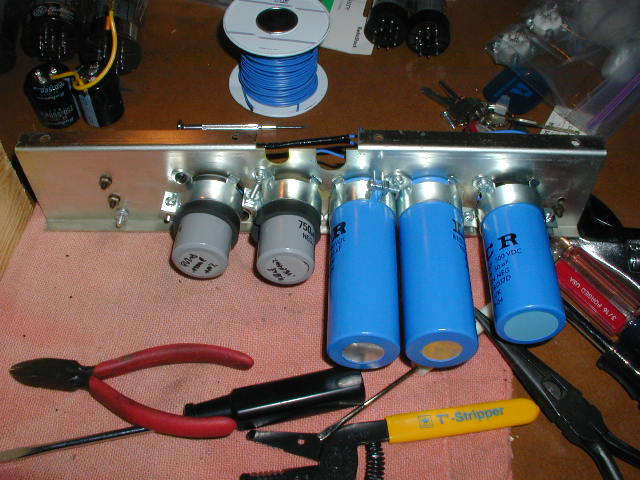
It all fits. :> D He uses 820 μF. caps in the doubler stack. The principal filter choke is the excellent OEM part. Jim gains space on the cap. bracket by moving the bias supply off of it. Capacitance galore in the doubler, reservoir, and decoupling positions. Something in excess of 130 WPC pulse is available. That PSU has brass monkey cojones. The "hash" filter is a small refinement of his already very nice work.
The linked cap. bracket photo is somewhat dated, in that parts brands have changed over time. The pair of isolated gray caps. are the doubler stack.
Eli D.
According to my sim, the original Cit II PS has a significant impedance bump around 25-30 Hz. That's due to the factory values for the choke and reservoir cap. Making the reservoir larger mitigates that issue. Anyway, this is very different than what I thought you were describing when you mentioned adding a hash filter. The model I posted is valid for that, but it doesn't include a large smoothing capacitor (reservoir) afterwards. I might have to bite the bullet and take the same approach in my rebuilds. The 500mH chokes will work if I do that, it's just a matter of adding enough output capacitance to push the resonance bump to a lower frequency. Good discussion, thanks!
--------------------------
Buy Chinese. Bury freedom.
Edits: 04/01/17
| FAQ |
Post a Message! |
Forgot Password? |
|
||||||||||||||
|
||||||||||||||
This post is made possible by the generous support of people like you and our sponsors: