 |
Audio Asylum Thread Printer Get a view of an entire thread on one page |
For Sale Ads |
|
|
Audio Asylum Thread Printer Get a view of an entire thread on one page |
For Sale Ads |
97.95.43.235
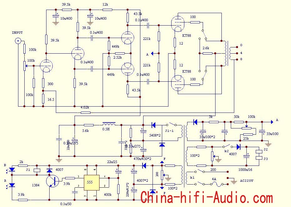
These amps don't sound too bad actually.They use cores from Eastern Europe or Japan and I believe it's dual mono which for the money isn't bad. I'm looking at the circuitry and it uses doublers in the HV supply as well as the time delay but I wonder what circuit that time delay feeds. I'm assuming it's filament but there is also a second filament source or board as well as the negative bias circuitry above it.
I wonder they didn't use the choke for the output section as opposed to using it for the phase-splitter and driver?
"For every complex problem there is an answer that is clear, simple, and wrong" H. L. Mencken
Follow Ups:
A 100K pot and a 100K resistor to the INPUT of the first tube, sounds like pure "doggie doo" , because of the series resistance connections.
Cool, this little amp gets into a goofed-up mode, even before the very first stage, from the get-go !!!
Jeff Medwin
Jeff-
Seems to me you are in the process of building a passive attenuator using a potentiometer.
What makes that better than having a pot on the input of the amp?
Wouldn't the capacitance of the RCA interconnects make your solution a negative compared to being on the input of the amplifier?
At least with the schematic. The OPT secondary is not connected to the amp commen (ground). Feedback isn't going to work worth a damn that way.EDIT, I just noticed the amp commen is not tied to the power supply either!
Yes any experienced PP builder will easily see that and fix it. But a novice may build this just as shown.
Edits: 01/19/17 01/19/17
gusser-
what other negatives are there with not connection the opt secondary to the amp common ground?
Aside from the feedback not having a return beyond the capacitance of the secondary winding to the transformer case, some also consider the lack of secondary ground a safety hazard should the transformer develop a primary to secondary short.
thanks gusser!
This thing is pretty basic:
The coupling caps are all 0.1, no attempt to spread out poles by using different value caps. 221k grid resistors are really high for fixed bias, I think KT88 datasheet says max. 100k for fixed bias. BAD. Potential for thermal runaway of output tubes.
No compensation components for the feedback circuit, control bandwidth, etc.
The voltage divider on the input looks like cheese too, to make up for the amplifier having too much gain to begin with.
Single fixed bias pot, no chance to balance current if output tubes slightly mismatched.
Looks to me like someone took a williamson and removed all the intelligence from it.. I wouldn't buy this amp, there's too many designs out there by people who took more interest in what they were doing.
M O N E Y (and space)
A 20mA choke is a hell of a lot cheaper (and smaller) than a 300mA choke.
Push pull amps like this can get away with simple filters for the output section due to noise cancellation of the push pull pair.
I suspect the time delay operates switch j1-1 on the V-doubler.
I suspect the time delay operates switch j1-1 on the V-doubler.
That would be my thought as well but I wonder how it gets there? It doesn't show any connection to the switching on the high voltage B+ doubler.Maybe a more thorough schematic would show that.
"For every complex problem there is an answer that is clear, simple, and wrong" H. L. Mencken
J1 in the time delay circuit (bottom left) is a relay and it tosses J1-1 in the B+ line.
Tre'
Have Fun and Enjoy the Music
"Still Working the Problem"
Post a Followup:
| FAQ |
Post a Message! |
Forgot Password? |
|
||||||||||||||
|
||||||||||||||
This post is made possible by the generous support of people like you and our sponsors: