- Posted by Boulder Bob (A) on April 21, 2017 at 05:30:38
Is 1000 Hz with 6 dB/octave correct? I saw a spec for 1100 Hz posted. It appears the First Watt can be set up for a variety of frequencies but they do give sample instructions for 1000 Hz in the manual.Will I be able to set up an active XO by ear? My woofer and tweeter amps are not the same.
I am borrowing a frequency analyzer today. Will I need a frequency sweep source? Is there a download available for this?
Will I start with the level controls on the XO all the way up and adjust from there? There are no level controls on my power amps.
How do I make sure the woofers are in phase with the tweeters? I have an app on my Android phone called Polarity Checker but have not tried to use it.
Any advice greatly appreciated!
Edits: 04/21/17Follow Ups:
- PLLXO for Tympani ID - neolith 15:57:24 04/23/17
(0)
- In Reply to: RE: First Watt B4 arrives today - setup questions for Tymp I-Ds posted by Boulder Bob on April 21, 2017 at 05:30:38
I dug up a spreadsheet from a few years ago. I plugged in the values for your setup assuming your preamp has an output impedance of 200 ohms and the amps have input impedances of 50K. Look at the "Generic" column on the far right. There is an instruction sheet to guide you through any changes. The spreadsheet is written for LibreCalc which is free.
Sorry I don't have an Excel version but if you are really interested I could whip it up for you. I just found an Excel Version.
PLLXO LibreCalc
PLLXO Excel

I married the perfect woman. The downside is everything that goes wrong is my fault.
Edits: 04/23/17 04/24/17
- RE: First Watt B4 arrives today - setup questions for Tymp I-Ds - neolith 08:00:51 04/21/17
(0)
- In Reply to: RE: First Watt B4 arrives today - setup questions for Tymp I-Ds posted by Boulder Bob on April 21, 2017 at 05:30:38
Since your amps are different, check the gains - they need to be the same -- and use your XO to adjust. Remember gain is not the same as sensitivity. As far as polarity goes, since the LP and HP filters are both 1st order, the polarity of the tweeter and woofer is irrelevant -- the phase will always differ by 90 degrees.
If you are using a frequency analyzer then you want a pink noise generator. There are several available on line, just Google. However the best program IMO is REW5 which is free and includes a function generator. To get the best out of the REW5 you will want a calibrated mike. I use the UMM-6 from PartsExpress which now is about $80. This will not only help you setup the crossover but also help you position the speakers and adjust the sub if you have one. BTW you may need a cheap soundcard if your computer does not have line outputs. I use a Behringer UCA-222 which is about $30.
And yes you can do a pretty good job with just your ears which is what the vast majority do.
I married the perfect woman. The downside is everything that goes wrong is my fault.
Edits: 04/21/17 04/22/17
- RE: First Watt B4 arrives today - setup questions for Tymp I-Ds - Satie 07:45:49 04/21/17
(0)
- In Reply to: RE: First Watt B4 arrives today - setup questions for Tymp I-Ds posted by Boulder Bob on April 21, 2017 at 05:30:38
If you are going to do an equidistant placement of the panels then a 1khz symmetrical crossover will do the job. In the original it seems the high pass and low pass use slightly different frequencies with the LP at `~1100Hz and HP at ~1000hz.
- RE: First Watt B4 arrives today - setup questions for Tymp I-Ds - Davey 06:49:37 04/21/17
(15)
- In Reply to: RE: First Watt B4 arrives today - setup questions for Tymp I-Ds posted by Boulder Bob on April 21, 2017 at 05:30:38
That's a horribly expensive and fancy device just to perform a simple first-order crossover. :)
A simple resistor/capacitor network (about five bucks) will do the same thing.
But yes, 1000Hz is where you should set both filters. That's pretty darn close to the 1D stock curves.
Dave.
- RE: First Watt B4 arrives today - setup questions for Tymp I-Ds - BDP24 21:04:32 04/21/17
(2)
- In Reply to: RE: First Watt B4 arrives today - setup questions for Tymp I-Ds posted by Davey on April 21, 2017 at 06:49:37
I know the formula for creating a 1st-order high-pass filter via a single capacitor, plugging in the power amps input impedance and the desired x/o frequency. What is the formula for the corresponding 1st-order low-pass filter? Can the low-pass be accomplished just as easily, with a single capacitor on the power amps input jacks, or are more parts required, like a resistor as well as a cap?
Edits: 04/21/17
- RE: First Watt B4 arrives today - setup questions for Tymp I-Ds - Davey 06:35:57 04/22/17
(0)
- In Reply to: RE: First Watt B4 arrives today - setup questions for Tymp I-Ds posted by BDP24 on April 21, 2017 at 21:04:32
Same formula. No, you can't just a single (shunt) capacitor at the input jacks because you need a series element (resistor) to create a low-pass filter.
At speaker-level you would use an inductor, but you can't do that at line-level because the L value would be very large.You need to fully characterize both power amps input R and the preamp output R before even attempting this.
Dave.
Edit: Sorry for the duplicate information, Neo beat me to it and posted while I was typing.
Edits: 04/22/17
- RE: First Watt B4 arrives today - setup questions for Tymp I-Ds - neolith 06:31:24 04/22/17
(0)
- In Reply to: RE: First Watt B4 arrives today - setup questions for Tymp I-Ds posted by BDP24 on April 21, 2017 at 21:04:32
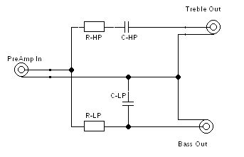
You need to use a series resistor and shunt cap for the LP, creating a voltage divider. The resistor will introduce a insertion loss. You can match the insertion loss on the HP by also using a resistor but as you said a single series cap is sufficient.
I married the perfect woman. The downside is everything that goes wrong is my fault.
- RE: First Watt B4 arrives today - setup questions for Tymp I-Ds - Davey 06:35:57 04/22/17
(0)
- RE: First Watt B4 arrives today - setup questions for Tymp I-Ds - Boulder Bob 10:53:46 04/21/17
(11)
- In Reply to: RE: First Watt B4 arrives today - setup questions for Tymp I-Ds posted by Davey on April 21, 2017 at 06:49:37
I considered going passive - the input and output impedance specs are not available for the two woofer power amps I will be using, made by Professional Systems Engineering (PSE), one amp bridged per woofer. PSE is no longer in business and I inquired locally with some techs about trying to measure impedance and didn't get anywhere. I am getting the First Watt on a 10 day approval so if it doesn't do what I want, I may investigate some other woofer amps with known specs.
- RE: First Watt B4 arrives today - setup questions for Tymp I-Ds - Davey 11:18:05 04/21/17
(10)
- In Reply to: RE: First Watt B4 arrives today - setup questions for Tymp I-Ds posted by Boulder Bob on April 21, 2017 at 10:53:46
Measuring an unknown input impedance is easily done. I have a little box (with a variable resistor) I constructed many years ago to accomplish this. :)
http://www.sengpielaudio.com/calculator-InputOutputImpedance.htmThe power amplifier output impedance is irrelevant since it will be a small fraction of the speaker load.
Cheers,
Dave.
Edits: 04/21/17
- RE: First Watt B4 arrives today - setup questions for Tymp I-Ds - Boulder Bob 11:32:26 04/21/17
(9)
- In Reply to: RE: First Watt B4 arrives today - setup questions for Tymp I-Ds posted by Davey on April 21, 2017 at 11:18:05
Hmmmm - maybe I should rethink this active vs passive XO conundrum...
- RE: First Watt B4 arrives today - setup questions for Tymp I-Ds - BDP24 21:24:10 04/21/17
(8)
- In Reply to: RE: First Watt B4 arrives today - setup questions for Tymp I-Ds posted by Boulder Bob on April 21, 2017 at 11:32:26
Bob, I too got myself a B4. I justified doing so by the fact that I have a number of different speakers with which to use it (old Quads, ET LFT-8b, Maggie Tympani T-IV, a couple of pair of small monitors), all needing different x/o frequencies and perhaps slopes. But your Tympani T-I's can be filtered with just a couple of passive parts, avoiding extra electronics and inter-connects, and their cost. But the B4 is sure a well-designed and versatile product, isn't it?!
- RE: First Watt B4 arrives today - setup questions for Tymp I-Ds - Satie 22:23:45 04/21/17
(7)
- In Reply to: RE: First Watt B4 arrives today - setup questions for Tymp I-Ds posted by BDP24 on April 21, 2017 at 21:24:10
You can use this URL
Note that you don't have to know what the input impedance of the bass amp is, so long as it isn't very unusual.
If you want to add level controls you add the bass level control pot after the low pass filter section and the highs level pot before the high pass filter section.
While I agree that the B4 is overkill for a T 1 D crossover, It is convenient and does not require you to learn how to solder and mount parts or calculate filters and components. It is well built and has a small sonic signature.
- RE: First Watt B4 arrives today - setup questions for Tymp I-Ds - Davey 06:40:16 04/22/17
(6)
- In Reply to: RE: First Watt B4 arrives today - setup questions for Tymp I-Ds posted by Satie on April 21, 2017 at 22:23:45
You won't need a level control on the low-pass section because the RC network will create an insertion loss. Even adding one to the high-pass filter section can get a little tricky because it alters the source resistance.
The t-linespeakers link information is not incorrect, but it's much too "textbook." A person will most likely need to adjust the component values because of capacitor standard values, relative attenuation, etc, etc.
Dave.
- RE: First Watt B4 arrives today - setup questions for Tymp I-Ds - BDP24 17:48:43 04/22/17
(5)
- In Reply to: RE: First Watt B4 arrives today - setup questions for Tymp I-Ds posted by Davey on April 22, 2017 at 06:40:16
Thanks for all the info guys! If a 1st-order high-pass filter is all one requires for the main speakers, it seems like going with that passive filter for them, with an active, adjustable-level low-pass x/o for the subs or woofers would be an effective, low-cost approach for the op. The B4 does that and more, but at around a grand is perhaps not justifiable, cost-wise. In the case of the Tympani T-IV, the old Dahlquist DQ-LP1, with it's passive 1st-order filter (whose hp filter frequency can be changed by the value of the capacitor installed) and an active 3rd-order low-pass (what the T-IV requires for bi-amping) and level control is just what is called for. If anyone is looking for a DQ-LP1, I just happen to have one (in great shape, with original factory carton and instruction manual) I can let go ;-)---Eric.
Edits: 04/22/17 04/22/17
- RE: First Watt B4 arrives today - setup questions for Tymp I-Ds - Davey 20:54:10 04/22/17
(4)
- In Reply to: RE: First Watt B4 arrives today - setup questions for Tymp I-Ds posted by BDP24 on April 22, 2017 at 17:48:43
Unfortunately, that unit was not designed for this application.
It was designed primarily for sub/main speaker crossover duties where the main speaker already has a native 2nd-order roll-off. Thus, you would achieve a symmetric 3rd-order slope crossover using the electrical 3rd/1st electrical slopes of the Dahlquist unit.
So, yes, in the case of the T-IV it might work effectively, but NOT in the case we're talking about here with the I-D. Two completely different animals with completely different line-level solutions required.
Dave.
- RE: First Watt B4 arrives today - setup questions for Tymp I-Ds - BDP24 00:24:15 04/23/17
(3)
- In Reply to: RE: First Watt B4 arrives today - setup questions for Tymp I-Ds posted by Davey on April 22, 2017 at 20:54:10
Exactly Dave. For the op's Tympani T-1, a symmetrical 1st-order x/o is required for both the high and low pass filters. At the time of it's original manufacture, the T-1 was being distributed by Audio Research, whose PC-1 passive x/o was designed expressly for that application. It created a 1000Hz x/o point, with four level controls, one each for left and right channels/high and low pass outputs.
- RE: First Watt B4 arrives today - setup questions for Tymp I-Ds - Davey 07:47:37 04/23/17
(2)
- In Reply to: RE: First Watt B4 arrives today - setup questions for Tymp I-Ds posted by BDP24 on April 23, 2017 at 00:24:15
I would hang onto that Dahlquist unit. That's a nicely conceived unit and could come in handy in the future.
Dave.
- RE: First Watt B4 arrives today - setup questions for Tymp I-Ds - BDP24 17:45:36 04/24/17
(1)
- In Reply to: RE: First Watt B4 arrives today - setup questions for Tymp I-Ds posted by Davey on April 23, 2017 at 07:47:37
Good point Dave. That's why I still have the DQ-LP1! I kept my copy of Frank Van Alstine's plans for his upgrade modification to it. One thing to do is just not use the high-pass inputs---the capacitor is uses for filtering can just as easily be installed on the power amp input jacks, saving an extra set of inter-connects. Then use the active 3rd-order low-pass inputs only. That control has an adjustable frequency range, though not nearly as wide or precise as that of the First Watt B4.
Edits: 04/24/17 04/24/17
- RE: First Watt B4 arrives today - setup questions for Tymp I-Ds - Davey 20:55:11 04/24/17
(0)
- In Reply to: RE: First Watt B4 arrives today - setup questions for Tymp I-Ds posted by BDP24 on April 24, 2017 at 17:45:36
Well, it's hardly going to make any difference unless you have interconnects that are a mile long.
Installing the capacitor internal to the DQ-LP1 is preferred as it allows to use the shunting resistor location so you can fine-tune while still using standard value capacitors.
Dave.
- RE: First Watt B4 arrives today - setup questions for Tymp I-Ds - Davey 20:55:11 04/24/17
(0)
- RE: First Watt B4 arrives today - setup questions for Tymp I-Ds - BDP24 17:45:36 04/24/17
(1)
- RE: First Watt B4 arrives today - setup questions for Tymp I-Ds - Davey 07:47:37 04/23/17
(2)
- RE: First Watt B4 arrives today - setup questions for Tymp I-Ds - BDP24 00:24:15 04/23/17
(3)
- RE: First Watt B4 arrives today - setup questions for Tymp I-Ds - Davey 20:54:10 04/22/17
(4)
- RE: First Watt B4 arrives today - setup questions for Tymp I-Ds - BDP24 17:48:43 04/22/17
(5)
- RE: First Watt B4 arrives today - setup questions for Tymp I-Ds - Davey 06:40:16 04/22/17
(6)
- RE: First Watt B4 arrives today - setup questions for Tymp I-Ds - Satie 22:23:45 04/21/17
(7)
- RE: First Watt B4 arrives today - setup questions for Tymp I-Ds - BDP24 21:24:10 04/21/17
(8)
- RE: First Watt B4 arrives today - setup questions for Tymp I-Ds - Boulder Bob 11:32:26 04/21/17
(9)
- RE: First Watt B4 arrives today - setup questions for Tymp I-Ds - Davey 11:18:05 04/21/17
(10)
- RE: First Watt B4 arrives today - setup questions for Tymp I-Ds - BDP24 21:04:32 04/21/17
(2)
- RE: First Watt B4 arrives today - setup questions for Tymp I-Ds - Boulder Bob 05:53:37 04/21/17
(0)
- In Reply to: RE: First Watt B4 arrives today - setup questions for Tymp I-Ds posted by Boulder Bob on April 21, 2017 at 05:30:38
I found these files for frequency sweeps:
http://www.audiocheck.net/testtones_sinesweep20-20k.php
| FAQ |
Post a Message! |
Forgot Password? |
|
||||||||||||||
|
||||||||||||||
-
To view your new posting or follow-up, click on the RELOAD or REFRESH button on your browser.
This post is made possible by the generous support of people like you and our sponsors:

[
[ General ] [ Speakers ] [ Tubes ] [ Vinyl ] [ Digital ] [ Hi-Rez ] [ Video Asylum ] [ Cables ] [ Tweaks/DIY ] [ Music ] [ Films ]