- Posted by jdrouin (A) on March 11, 2017 at 14:42:36
In Reply to: RE: TFA-204 300B Operating Points posted by jdrouin on March 07, 2017 at 12:34:03
After doing some more digging, I found a thread here where Mike indicated the DC series resistance of the TFA-204 primary is 140 ohm.Also, the previous LTSpice schematic contained an error. I though I had to enter the 5VDC voltage source for the 300B filament, but that is assumed by the software. Instead, you treat that as a cathode. So I removed the 5VDC source and added the cathode resistor with bypass capacitor that I had mistakenly left off before.
A member of diyaudio (where I'm also modeling a Fi Primer 300B with the TFA-204) helped me figure out that, since the primary inductance is 10H, and the turns ratio is 18.26, the inductance for the secondary should be 0.03H in the sim: 10/18.26^2 ~ 0.03H.
With all of that information entered into the model, and with a hypothetical rectified B+ of 358V after the PS (not modeled yet) and a cathode resistor value of 1.2K, we get 350V on the plate and current that peaks to about -61V. The sine wave of current through the TFA-204 primary goes from about -41mA to -61mA peak-to-peak, which seems close to the 8W option originally posted (350V, 60mA, -74V, into 3K = 8w output).
Does that seem right?
Does the 300B datasheet rating mean -60mA RMS or peak?
I don't know what the grid voltage is right now, and I still have to model the power supply.
Also, if this really results in 8W output, it's pushing up against the maximum of the TFA-204 power rating. Wondering if I should aim for the 300V, -50mA, 6W option.

Edits: 03/11/17 03/11/17 03/11/17 03/11/17 03/11/17Follow Ups:
- RE: First Simulation - jdrouin 12:05:24 03/12/17
(3)
- In Reply to: RE: First Simulation posted by jdrouin on March 11, 2017 at 14:42:36

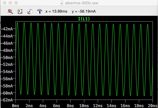
Learning more as I go along. I decided to set the voltage and frequency at the signal input source to 0 and then adjust the cathode resistor to 1K on the 300B to get an idle current of 60mA (plate voltage is still 350V).Then I reintroduced a signal of 0.7V @ 1kHz, resulting in a current sine wave that neatly reaches -50mA to -70mA peak-to-peak (shown in graph above), exceeding the TFA-204's 60mA rating by 10mA.
A 1V signal produces -45mA to -75mA peak-to-peak.
Is this workable, or would it cause core saturation in the TFA-204?
Edits: 03/12/17 03/12/17 03/12/17
- RE: First Simulation - Paul Joppa 20:38:23 04/07/17
(0)
- In Reply to: RE: First Simulation posted by jdrouin on March 12, 2017 at 12:05:24
The 60mA rating is for quiescent current (no signal). The AC instantaneous current will be greater, but still within the spec - that 60mA rating allows plenty of signal AC current before saturation issues.
- RE: First Simulation - Gordon Rankin 16:28:40 03/13/17
(1)
- In Reply to: RE: First Simulation posted by jdrouin on March 12, 2017 at 12:05:24
Ok,
First off, remember a class a amp operates full with 0Vac input. So yes bias the 300B at 60ma. You don't need to worry about the AC-PP current as that is not an issue. Remember class A 0Vac input is when the tube is running at max power.
Second if you are doing a simulation you need a ton more data. Remember the Rp of the tube effects the results as it is in a sense in parallel to the tube.
Also remember when approaching 60% of the bias voltage in an AC input signal to the 300B that the grid will start to draw DC current which will increase the voltage across the grid resistor and rebias the tube.
You do know that your going to need a boat load more AC voltage input to the 300B. Looks like your gain tube is going to result in like 18Vacrms gain and the 300B is going to need 51.63Vacrms into the 300B to get to 8W's. That means you need about 3Vacrms input to make that work.
Also work in voltage, tubes are voltage devices, working in current is just going to confuse you.
Thanks,
Gordon
J. Gordon Rankin
- RE: First Simulation - jdrouin 18:06:45 03/13/17
(0)
- In Reply to: RE: First Simulation posted by Gordon Rankin on March 13, 2017 at 16:28:40

Thanks, Gordon. Several members at diyaudio helped me figure out that the datasheet numbers for, say, plate voltage actually mean plate-to-cathode. So, the 350V operating point actually requires a B+ supply of 435V, which puts 425V on the plate after passing through the 140 ohm primary of the TFA-204, requiring a 1.25K cathode resistor to maintain a 60mA idle current. This combination also results in ~75V on the cathode: 425V-75V = 350v.
So the attached, revised schematic seems to fit the 350V/60mA into 3K operating slot on the WE datasheet.
I've been simming other circuits too, like the Fi Primer 300B, and have been able to come up with a viable power supply based on the resistance across the 300B and the OPT at those voltages (5.8K on the 300B, 1.25K on the cathode, 140R on the OPT = 7190R for the final resistor in PSUD2). It's been cool to see how the results in PSUD2 match the ones I get in LTSpice.
Can't model the power supply for George's amp in PSUD2, though, because his choke is in the ground leg and the software doesn't offer that option. So I think I'll first breadboard a Fi Primer 300B, since it's a little more straightforward, before attempting George's design.
Now that I have a little experience with modeling this stuff, the mathematics in Morgan Jones' book will make more sense, so I've started reading that too.
- RE: First Simulation - jdrouin 18:06:45 03/13/17
(0)
- RE: First Simulation - Paul Joppa 20:38:23 04/07/17
(0)
Post a Followup:
| FAQ |
Post a Message! |
Forgot Password? |
|
||||||||||||||
|
||||||||||||||
-
To view your new posting or follow-up, click on the RELOAD or REFRESH button on your browser.
This post is made possible by the generous support of people like you and our sponsors:

[
[ General ] [ Speakers ] [ Tubes ] [ Vinyl ] [ Digital ] [ Hi-Rez ] [ Video Asylum ] [ Cables ] [ Tweaks/DIY ] [ Music ] [ Films ]