 |
Audio Asylum Thread Printer Get a view of an entire thread on one page |
For Sale Ads |
|
|
Audio Asylum Thread Printer Get a view of an entire thread on one page |
For Sale Ads |
In Reply to: Horn phase posted by Wayne Parham on September 14, 2003 at 22:29:09:
Hi WayneI don�t know the dimension of the horn you have modeled but there are a few things one can tell about it from the curves.
It would appear to be a horn that is 1 / 2 wl or longer vs the minimum 1 / 4 wl length (a guess based on the spacing of the ripples).
Based on the frequency response ripples, I would guess the driver is not a good match and / or the mouth is not large enough. This would not be a high efficiency horn.
Response ripples in the output can be caused by a mis-match at either end of the horn IE: mouth too small or driver not suitable. The latter is where the M.L. math is useful.
Fwiw, simpler models (like spice models or the transmission line model I use) also tend to over state the �Q� of such ripples compared to measured results (suggesting there are un-accounted acoustic losses).While this model show ripples in the output up to the high cutoff, it is not necessary to have them when everything is right.
The thing is, whatever the horns impedance is, it is not the definition of what comes out the mouth of the horn.
The horn has an acoustic �impedance� curve, which changes most rapidly in the range near the lf cutoff. Driving that horn is a driver that also has an acoustic impedance and reactance.
When the source and load (driver and horn) are matched, there can be a considerable change in either with a minimum effect on the output.
For example with a nominally matched source and load, one can change the load to 2X or 1 / 2 the original and see less than a 2 dB change in output power. Contrast that to the 6 dB spread when a voltage source is used on a changing load.
Since the driver�s impedance is in series, the effects of phase shift are also reduced (like any reactance in series with an R compared to just the reactance).
The driver also has reactance, however it is customary to make this a conjugating quantity, either by proper sizing of the driver properties and rear volume and / or adjusting the horn flare hyperbolic constant which shapes the rate of change of resistance and reactance (reactance annulling)Anyway, I have to help with some homework so I have to keep this short.
Since you have a way to model horns, how about if I see if I can find parameters which result in little or no ripple in the response. I will post the specifics (since I can�t post images) and you take your program or Mc Beans and see how it looks. Conversely, if this is a real horn you have, let me know the specifics and I will see if I can find a driver which is a better fit.40 to 400 Hz is wider bandwidth than most of the single horns I do but I think flat response in that range would be possible.
Without ripples in the output, there will be no ripples in the output phase as well.
With a horn that is more resistively dominated, the phase will be around zero at the output (after all the fixed delays are removed ala Heyser) and the result is also a more efficient horn
Remember it is only the efficient horn which is resistively dominated and having an acoustic phase around zero degrees.Shortly at the new web site there will be measurements for the Bdeap, while narrower BW than your example, acoustic phase is around zero from somewhat above low cutoff through its operating band.
Also if I recall, the BT-7 response curve also has the acoustic phase plotted.
Got to runTom

Follow Ups:
Perhaps you will post some examples of horns that have zero phase throughout their passbands. You have promoted time alignment as one of your main marketing strategies, so I can see that you are zealous about it. But I don't find it to be particularly accurate to state the generalization that horns are resistive and therefore phase is zero. Frankly, I always considered your "zero-phase" assertion to be a generalization at best.Horns do become more resistive at higher frequencies, and so there is some reason to mention this general trend. But the fact is that they are not purely resistive, and really aren't even predominantly resistive. So for you to say "horns are resistive" in an argument about phase or acoustic impedance is an overgeneralization that leads people to an inaccurate conclusion.
So I suggest that you back up this assertion with some demonstratable facts; Even when modeling hypothetical infinite horns there is a large reactive component, so it will suprise me to see evidence to the contrary, particularly on a finite horn. But you'll excuse me if I won't accept your measurements as evidence.
Dimensions and specifications would be acceptable, so that they can be used for modeling purposes. Or independent measurements from an impartial lab would be fine. But I think you can understand why I might be a bit skeptical of data coming from you after the comments you've made on this thread and others.
You might not accept my measurements either. I typically don't publish measurements for this very reason, and would prefer that anything we use as evidence come from an independent and impartial source. But anyone interested can use these discussions as "seeds for thought" and do their own analysis. Below are measurements of several horns connected directly to an amplifier without any crossover or electronic reactive components in the circuit, not even a protective capacitor.
Amplitude response is shown in black, phase is gray.
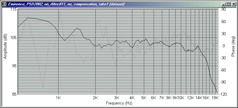
Altec 811
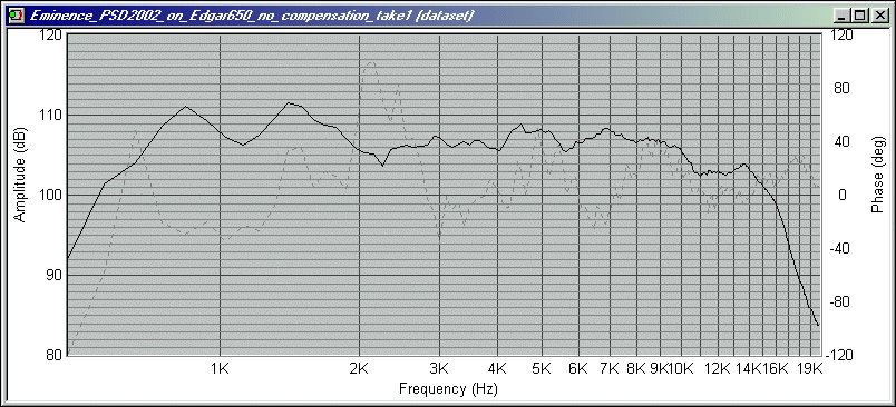
Edgar 650
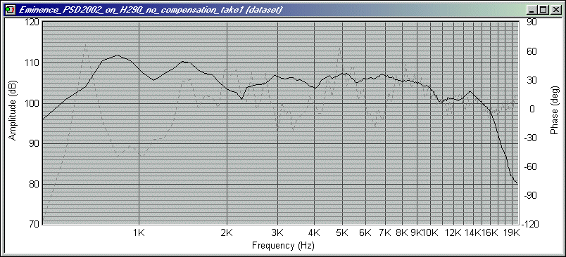
Eminence H290
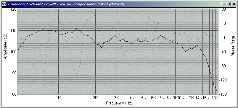
JBL 2370
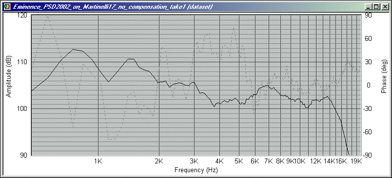
Martinelli 17"
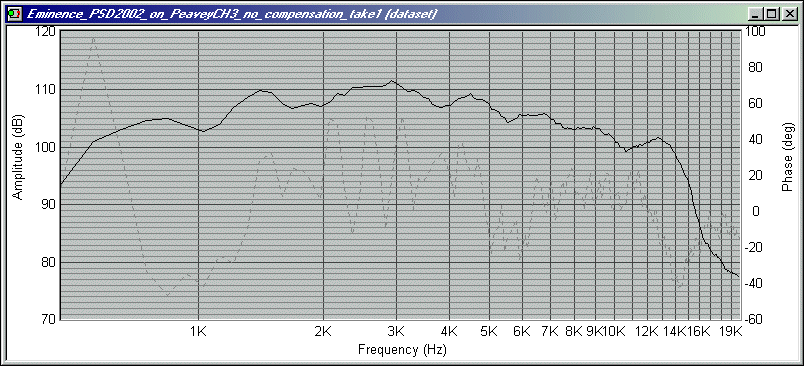
Peavey CH-3

This post is made possible by the generous support of people like you and our sponsors: