 |
Audio Asylum Thread Printer Get a view of an entire thread on one page |
For Sale Ads |
|
|
Audio Asylum Thread Printer Get a view of an entire thread on one page |
For Sale Ads |
24.108.53.95
Hi,
I am about to embark on building my first set of speakers, a 59 y.o. rookie haha. Fortunately I have the skills to build my cabinets but I no knowledge with the marriage of the components. I have a pair of altec 414-16b's, (16 ohm) and a pair of 902-8t 511b's, (8 ohm). I guess what I was hoping to find out is what is required to get the optimum out of what I have. Has anyone done similar or have the knowledge to share.
Thanks,
Joe
Follow Ups:
Bi-amplify with active crossover (4th order LR 1.2k to 1.6kHz) and use a compression driver compensation circuit on the horn (Altec 30923 w/L-PAD).
The cabinet could be a ported box 3.5 - 4 cu. ft. tuned to around 40 cycles.
That would go down to -3dB @ 70 cycles or so in room.
Blend in an active subwoofer for the last few octaves.
I had similar setup for 414-8B/811B+808-8A.
If you have accurate T/S parameters for the 414's, try WinISD freeware to design the box.
And you can make some DIY Altec Laguna's! That would sound really nice since they are corner placement firing out that will have a nice coverage area.
your'e right, just checked out some Lagunas on google. I learn something new everyday.
thanks
Hi,
I replied to your other thread at diyaudio here:
Check out this thread for some ideas
on 414 implementations.
Once you decide on, and build, a cabinet,
you can start listening to a wide variety
of crossover points. First order is simple
and can be very beautiful. You will find out
which driver is most interesting to you
in a given frequency range.
I often prefer a larger coil and smaller cap
than what comes up on the calculator values.
great stuff Mats
thanks
I strongly suggest you give the Joe Roberts crossover approach (on the linked thread above) a try. It's very easy to do and there's a good chance you will be very pleased with it. I'm currently running GPA 414's full range with a TAD 2001 driver on a LeCleach horn with a first order high pass around 7200-7500 Hz. and an autoformer attenuator. I'm extremely pleased with how it sounds.
I've been working on doing the same thing. I have a pair of 414A's (two pair, actually, along with a pair of 414-8C's), 802-8D's, 32A horns, and NOS Gudeman PIO caps and a pair of custom 1dB step autoformers from Germany.
I'd love to hear how you wired your crossover.
The crossover I use just has a series cap, a variable shunting resistor across the autoformer inputs, and the autoformer itself.
I had a nice pair of matched oil caps tested at 2.07 uF. To get the desired crossover point around 7400 Hz, I needed a reflected impedance seen by the cap of about 10.4 ohms. The reflected impedance is the combined parallel resistance of the shunting resistor and the impedance seen from the autoformer. I'm using 9 dB of attenuation, which has a turns ratio of 2.833. The autoformer impedance is the 8 ohm driver x the square of the turns ratio, which equals 64 ohms. To get to my desired 10.4 ohm combined impedance, the shunting resistor needs to be 12.4 ohms.
By using a variable wire wound shunting resistor, I can tune the crossover frequency up and down using the same cap value. There are other ways to use an autoformer to get the desired results. This way seems to work well for me.
I have a pair of 3 ohm caps and 8 ohm 802D's as well as a pair of Werner Jagusch autoformers. I can't find it at the moment, but he shows a variable resistor in parallel with the primary of the autoformer. Presumably the autoformer will change impedance based on attenuation.
Bob Crites' 3636 autoformers are decent, have 1dB steps and currently sell for $35 each. One could use a copper alligator clip on a jumper to go around the taps. Sometimes its nice to use the high Z approach as smaller capacitors are generally less expensive than large. A swamping resistor across the driver can be used. Klipsch touted the high reflected Z reduced "Transient Intermodulation Distortion" (Otala).
3636 AUTOFORMER
Karlson Evangelist
What would the swamping resistor do in this case?
a swamping resistor would reduce the variation in impedance and possibly, response.
Karlson Evangelist
I have a pair of 3 ohm caps and 8 ohm 802D's with a pair of Werner Jagusch autoformers. In one of his diagrams he shows just such a variable resistor.
actually I now have 2 pairs of 414-16b's and the horns but nothing else .... lol, I'm looking for some schooling what would make this combo the best it can be. stay posted as so far there has been lots of good knowledge being shared.
Hmmm.. You could try the Rod Stewart Altecs, or a variant of it. But please, listen to the Faces instead of his disco daze phase if you finish your project. Just kidding.
Rod Stewart speakers sold by Richard's Gear?
also ask over at Lansing Heritagea crossover properly designed provides a good summation of the drivers and protects the delicate high frequency driver from being destroyed by lower frequencies.
LINKS - Lansing Heritage
http://www.audioheritage.org/vbulletin/forumdisplay.php?6-General-Audio-
DiscussionPi Speakers Audio Roundtable - you might PM Wayne
http://audioroundtable.com/forum/index.php?t=thread&frm_id=33
JE Labs
JE Labs 2-way altec horn page
http://jelabs.blogspot.com/2014/01/altec-2-way-horn-system-redux.htmlJE Labs update crossover to contour the HF
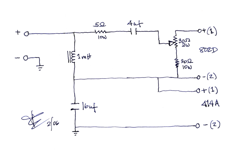
http://jelabs.blogspot.com/2014/01/altec-2-way-xo-update.htmlIF 414 variants are always 16 ohm (?), then I guess JE Labs early try with the N1600 would work to get you started - I'm not sure where to source the 30 ohm potentiometer. You could use two terminals of an L-pad in place of the pot.
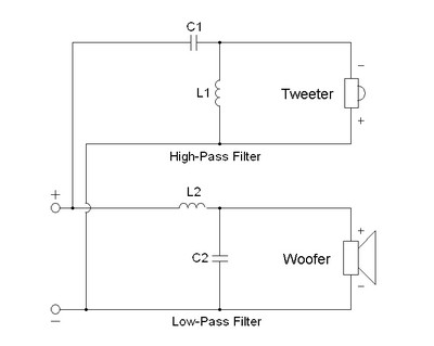
here's the basic diagram of a parallel 2-way crossover with 12dB electrical slopes - if inductor L1 and capacitor C2 were removed then it would be 1st order and 6dB per octave electrical slopes
here's a 6dB per octave series crossover schematic - JE Labs is using a simple series network with their 414 and Altec compression driver and claims it sounds better than whatever parallel network they tried
the series type works in a kinda see-saw fashion. At high frequencies, the coil's impedance is relatively high and the cap's impedance low and vice versa for low frequencies

Karlson Evangelist
Edits: 01/01/17 01/01/17 01/01/17 01/01/17 01/01/17
Post a Followup:
| FAQ |
Post a Message! |
Forgot Password? |
|
||||||||||||||
|
||||||||||||||
This post is made possible by the generous support of people like you and our sponsors: