 |
Audio Asylum Thread Printer Get a view of an entire thread on one page |
For Sale Ads |
|
|
Audio Asylum Thread Printer Get a view of an entire thread on one page |
For Sale Ads |
69.141.96.215
In Reply to: RE: Pilot SA260 amp Power Transformer toast? posted by Kirk57 on January 15, 2017 at 12:41:48
Kirk,
The other posters have you on a good path to resolving your issue.
Old cloth insulation IS a source of difficulty. The next time you have to deal with it, consolidate the stuff with clear nail lacquer and follow up with good heat shrink. The product is not especially flexible, but it will hold up for quite a bit of time. While it might fracture, the consolidated cloth fragments are held in place by the heat shrink.
BTW, are you planning a "stock" rebuild or are you interested in some modifications that will improve performance?
Eli D.
Follow Ups:
Eli-
Yes I'd like to improve performance but to be honest I'm not that skilled with tube circuits. I know Mike S has posted on power supply improvements via stiffening capacitance, but at my skill level I'd just be happy if the dang thing works and stops chewing through rectifier tubes.
The current production EH 5U4GB is pretty darned good and reasonably priced. If you want OS rectifiers, go with GE 5U4GBs, which are very nice and not silly expensive. Either way, Jim McShane is THE man to buy from.
Mikey has a penchant for using film caps. in the 1st filter position, when vacuum rectifiers are employed, and I agree with him. With that in mind, cement Mouser part # 75-MKP1848S65050JY5F to the underside of the chassis for that job. While the 5U4 pair could stand a larger capacitance, I don't want to overheat the precious OEM power trafo. We'll talk about the rest of the PSU, after I get a good look at some photos (top & bottom), which I request be posted.
There is extra filament current available in the power trafo that can be exploited to considerable advantage. Pilot's choice of a 12AU7 (shared between the 2 channels) for voltage amplifier duty, sucks a big wet one. :> (( The 'U7 triode is distressingly non-linear. Other than rewiring the heater connections, a 6CG7/6FQ7 drops in, without parts value changes. ;> )
Eli D.
What pictures are you requesting?
Right now I have the painted chassis, the transformers (not mounted) and a bunch of parts in a box. I can find pics of what it looked like originally if that's what you mean...
Original condition photos of both top and underside, please.
Eli D.
Bottom views: I didn't take one of the whole thing, but here are three shots that include everything. It was a mess, as you can see.
The perfboard with the diodes (which I think replaced the selenium rectifier) and some of the other work was done by a local tech years ago.


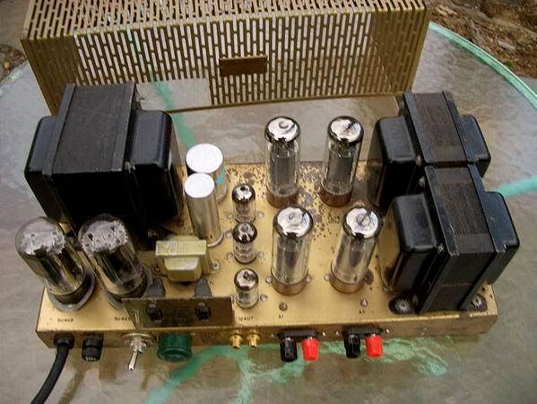
Top view: not mine, but it's the same amp:
http://i28.photobucket.com/albums/c207/whitese/pilotsa260.jpg
There are 2 "twistlok" (can) caps. whose diameters need to be measured. You will be increasing the amount of capacitance in the reservoir (C1B) and decoupling positions (C2A/C2B) using modern, clamp mounted, parts. Obviously, the clamp sizes appropriate to the chassis holes already present need to be acquired. I will "ping" Jim McShane to get his input on the subject.
Remember, C1A is being replaced by a film part that's cemented into place on the underside of the chassis.
BTW, I see only 1 diode in the bias supply. It was a nice touch on Pilot's part to full wave rectify the bias supply. Perhaps that area should be gone over too, since corners may have been cut.
Eli D.
The smaller twistlock can is 1" in diameter, the other is 1 3/8". Both are currently empty (I cut them apart and cleaned them so they could be stuffed with new caps as needed)
There is a second diode, hiding under the wire on the perfboard.
Stuffing and "gooping" is OK, but clamps are definitely more secure.
Let's see if Mr. McShane posts.
Eli D.
Post a Followup:
| FAQ |
Post a Message! |
Forgot Password? |
|
||||||||||||||
|
||||||||||||||
This post is made possible by the generous support of people like you and our sponsors:

