|
Audio Asylum Thread Printer Get a view of an entire thread on one page |
For Sale Ads |
|
|
Audio Asylum Thread Printer Get a view of an entire thread on one page |
For Sale Ads |
210.54.34.79
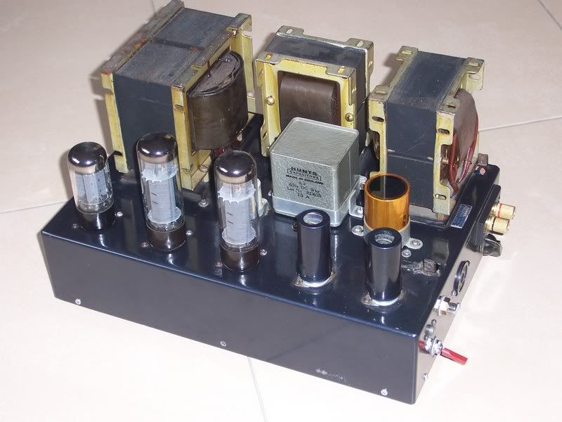
Hi all, need some help. In restoring my Beam Echo DL7 35 amps, it seems that my Hunts capacitors 4uF PIO items (the big grey cubes on the chassis in the example image below) are shot.
Does anyone know of a source for NOS replacements, closely matched? If not, what PIO replacements could you recommend?
My audio engineer tells me they should be really closely matched (5 or 10% if possible), 600V tolerant and fit under the hood.
Big J
"... only a very few individuals understand as yet that personal salvation is a contradiction in terms."
Follow Ups:
I see some mention of runaway voltages, that the 4uF hunt capacitors were bad, maybe that a couple of EL34's were found to be the problem in the end. Hard to make heads/tails of what the original problem/symptom was. Could be I didn't read closely enough.
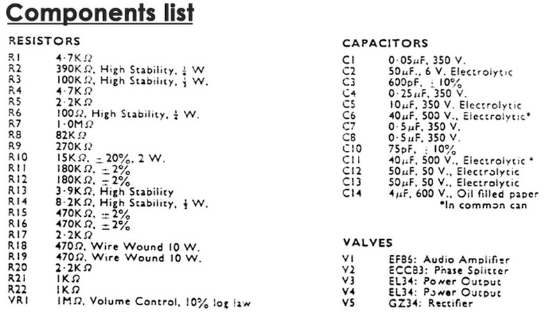
If you look over the parts list you will see that not all the capacitors in the power supply have the same voltage rating. If we assume all tubes work then the capacitors (going from output transformers, to ecc83, to ef86) will see decreasing voltages. But if, and this is a huge if, a tube (or tubes) fail to draw the expected current then voltages on some caps would be the same and therefore well above some of their ratings. If you are going to replace any of these caps I strongly encourage having a high enough voltage rating on all of them to withstand the maximum possible voltage. That would be 1.4 times the AC voltage the power transfomer delivers to the GZ34 plates.
I am hard pressed to think of any possible way for bad power supply caps to create an over voltage situation. They would create low voltage due to being leaky.....or excessive ripple voltage due to end of life aging (which typically cause hum out of the speakers). Over voltage (in the DC power supply) is almost always related to a lack of current draw. Sometimes tubes get weak. Sometimes they make poor contact in their tube sockets.
If the coupling caps to the EL34's leaked (C7 and C8) then the EL34's would draw too much current and DC voltages would be too low....at least for as long as the EL34's continued to work at normal values (which might only be seconds if C7,8 are really leaky).
There are a million ways for you to make your amp better. To do nothing more than replace all the parts with high end ones would be a mistake IMHO. In short take your time. Try to learn enough to understand pros and cons as you seek advice from those you "think" you can trust. The internet is very much a double edged sword in that regard. When in doubt I look first to proven audio designers. Paul Joppa is one such man still posting on audio asylum. IMHO taking advice from those that stand to profit (ones that sell parts/services) is akin to trusting the used car salesman's advice on which car is best.
Also give thought to how important the "original state" of the amp is to you. I would not think it had collectors value but I don't know. Moving to a larger chassis and making some circuit/parts changes could make a world of difference.
According to schematic and parts list I found, that 4uF cap is between a GZ34 and choke in the power supply. As long as it isn't plain old bad it wouldn't effect balance in any way. Just check to see if plate voltage on output tubes is close between the two amps.
What isn't clear is when your amp was made. It would help to know if it was 50's (which I doubt from picture) or the recent remake.
They are a ton of easily had parts that would work fine. A lot depends on if the 4uF value was picked to achieve a certain B+ voltage (somewhere between cap/choke input filter). If that is the case you want a 4uF poly or PIO cap. If not I'd go with a larger cap....around 20uF to 40uF. Again a poly or PIO. Motor run caps are an attractive choice and I like the older GE 27F series.
In no case can I see any upside to trying to locate something special given the caps location in the circuit. Yes you would like the caps to be close in value. But the real measure of that is what voltage you deliver to output transformers.
"According to schematic and parts list I found, that 4uF cap is between a GZ34 and choke in the power supply. As long as it isn't plain old bad it wouldn't effect balance in any way. Just check to see if plate voltage on output tubes is close between the two amps."
If the plate voltages on the output tubes were not close
a) would this matter, and
b) what would be the remedy if it did matter?
(The amps are immaculate, for the most part).
Big J
"... only a very few individuals understand as yet that personal salvation is a contradiction in terms."
It gets hard to write something reasonably short without knowing anything of your knowledge. A book or two might be in order. You can email me if you'd like.
The power supply transformer takes your wall voltage and "transforms" it to the various voltages required. It does this by the ratio of turns of insulated wire. If there was a fault in the transformer you could have anything from wrong voltages to excessive power draw....to smoke/fire. The best you can do is remove all tubes and compare voltages on all windings between the two amps. I'd want to see them under 10% and the closer the better.
The transformer sends AC voltage to the GZ34. The GZ34 turns that into DC voltage with "AC ripple voltage" imposed on it. We want to get rid of the ripple voltage. The capacitors (C14,11,6, and 5) perform this function (and other functions). We call them filter caps (but some are also decoupling caps). C14 should have a low impedance (name for AC resistance which involes a few parameters) path to ground for the AC ripple voltage but no connection to ground for the DC voltage. The larger the size of C14, the lower the impedance to ground at a given hertz. The use of a tube rectifier limits it size though. If C14 passed DC voltage to ground we would call it "leaky".
If C14 was leaky, and passing DC voltage ground, we would have a few symptoms, depending on how leaky it was. If minor, DC voltage would be low. If it leaked a little more power transformer might be warmer then normal, GZ34 life might be lower. If higher yet we might blow fuses. If C14 was warmer then normal, or the case distorted in shape, those would be warning signs.
If C14's impedance to ground had raised, due to age and such, ripple voltage would be higher than normal. An Oscope is the best way to see but some digital multi-meters can measure AC, DC, and hertz all at the same time. Make sure, because a lot of them can't, and I'd hate to see you get hurt.
C14 also controls "conduction angle" of the GZ34. If there was no C14, and L1 was big enough in relation to the load to meet "critical inductance", then the GZ34 would conduct for the entire sine wave (first one plate for half of it then the other plate for the other half of the transformer winding). DC voltage would be around 0.9 times the AC voltage from power transformer. You do have a C14 so the GZ34 only conducts for a part of the sine wave. The bigger C14 the smaller the conduction angle (time). DC voltage would be upwards of 1.4 times the AC voltage (neglecting GZ34 voltage loss which is a few tens of volts).
Given that the GZ34 only conducts for a brief period it passes a high current spike to C14 (and this causes problems). C14 must be charged with enough power (joules) to power the amp for the remainder of the sine wave during which the GZ34 is turned off. 4uF strikes me as rather small for that job given EL34 output tubes. There seems to be notes to the efect that C14 is dual case so it might actually be 8uF in total.
Next, after C14, DC goes to L1, a choke. The choke has a low resistance path to DC voltage so it lets it go right through. It has a high impedance to AC which is a function of size (henry) and hertz. It is also an energy storage device. Suffice to say it is there to reduce ripple voltage also.
Now we send DC voltage to output transformers. Because it is a push pull amp we don't need the same degree of ripple reduction that we would for a SET amp. Still I'd wish to see under a volt.
Then we go on the C11 and R10. This reduces the ripple voltage even more and adds some more energy storage to feed the ECC83 tube. As the ECC83 sees an audio signal its current goes up and down. This creates an AC voltage which is passed on through C7 and C8 to the EL34's. Some of this signal voltage is seen by C11/R10/C6 and they are the return path to ground for it. It that way they "decouple" this from the rest of the amp's circuit. Pretty much same thing for R9/C5 which feed the EF86.
So, to recap, these parts are there to:
a) reduce ripple voltage
b) to provide energy storage
c) to provide a return path for signal created voltages and decouple one stage from another
In regards to "balance" between amps I rate the following as most important:
a) matching of cathode bias resistors and plate load resistors
b) matching of tubes
c) matching of all other resistors
d) matching of coupling caps (C7 and C8)
e) matching of the power supply/decoulping caps is of little importance
Some general notes:
a) Many parts have improved greatly over the years. This is especially true of capacitors. Any electrolytic cap over ten years of age should be replaced with a 105C rated part.
b) Some parts have not improved. Vintage tubes and transformers are often superior.
c) Vinatge audio owners often fall in love with the sound of old out of tolerance/poor quality parts. When amps are "made better" with new parts they may feel "the vintage sound" has been lost and their amp is ruined. This is, of course, utter nonsense but be forewarned.
And would like to follow up with you offline. Thanks to both you, Michael and everyone else for offering this insight. I would like some books recommended to me, if you still feel inclined to do so. I think the time is right for me to take up the learning that I should have got going years ago.If I read you (and Michael Samra) correctly the Hunts capacitors would seem to be the least of my concerns at the moment, presuming they are not wildly out of spec. If so, I would likely see them maintained. That said, I'm not at all averse to modern parts being used sympathetically.
(BTW, your AA settings preclude me sending you an email. Perhaps you can email me at jsbkiwi@gmail.com).
Big J
"... only a very few individuals understand as yet that personal salvation is a contradiction in terms."
Edits: 02/28/15
Try this link. A very good collection that I am glad to see is still around. Crowhurst is a good place to start. I would also grab any old ARRL handbooks I find at second hand stores.
http://www.tubebooks.org/technical_books_online.htm
Good. Thanks.
Big J
"... only a very few individuals understand as yet that personal salvation is a contradiction in terms."
In the matter of books, the writings of Morgan Jones are very well thought of. I'm forever recommending the 1st or 2nd edition of "Basic Electronics for Scientists" by Brophy. The Brophy offering is quite rigorous and discusses both tubes and SS.Before visiting libraries and book sellers, Google NEETS. NEETS is U.S. Navy training material, which is available gratis on the WWW.
Eli D.
Edits: 02/28/15
I suspect I'll have to build a lot soon to 'anchor' some of this material.
Big J
"... only a very few individuals understand as yet that personal salvation is a contradiction in terms."
This is the 50s version, btw. Around 58, 59, I think.
Big J
"... only a very few individuals understand as yet that personal salvation is a contradiction in terms."
Agreed.
"If it measures good and sounds bad, it is bad; if it measures bad and sounds good, you have measured the wrong thing."
- Daniel R. von Recklinghausen
on ebay UK, If I were you, I'll get the original. That kind of cap is really tough, are you sure the problem is due to that 4uf cap?
suggested that the values were different enough to cause some issues of balance between channels. Not sure I understand what he means. I will look out for them and see if I can find a closely matched pair.
He's doing some generally repair work on the internal out-of-spec caps elsewhere in the circuit with modern equivalents for the time being. This will allow me to assemble NOS replacements for the internal pieces which are more in keeping with the vintage.
All of this triggered, apparently by two faulty RFT EL34s which permitted runaway voltages to creep into the circuit.
Big J
"... only a very few individuals understand as yet that personal salvation is a contradiction in terms."
Big J
When you say runaway voltages,are the tubes turning red or orange on the plates? Also,you may have to change the tubes if they were the ones giving you problems but if you don't at least change C7 and C8,you will have problems..You can use the Russian K40Y-9 pio caps which I use in everything and personally,they are more reliable than the Jensens because they are also hermetically sealed and don't leak like Jensens would.
You can also use a film caps for C7 and C8 like Steve suggested.
"If it measures good and sounds bad, it is bad; if it measures bad and sounds good, you have measured the wrong thing."
- Daniel R. von Recklinghausen
I wish I knew more about amp design than I do. Noted your K40Y-9 recommendation.
I've supplied my KT77s as replacements, since they're reissues and more are readily available.
Big J
"... only a very few individuals understand as yet that personal salvation is a contradiction in terms."
J
This is a very nice amp and it's very simple and easy to fix with just a DVM. There is no rocket science here.You change the original coupling capacitors out along with the any other capacitors on that board like the small electrolytics..Nichicon muses are wonderful for that but keep in mind you should check the resistors by lifting one side and measuring them with your ohmmeter.Many you can measure right in circuit without disconnecting them and they only need to read within 10% of the value if there is a silver colored band on them and within 5% if there is a gold colored band on them.
"If it measures good and sounds bad, it is bad; if it measures bad and sounds good, you have measured the wrong thing."
- Daniel R. von Recklinghausen
when I get it back after this repair is exactly this. Systematically go through the amp with some basic tools, measure and learn. Since I intend to keep these amps, it would pay to become very familiar with them. Then, perhaps, I can effect my own maintenance and repair myself in the future.
Thanks for your advice, Michael.
Justin.
Big J
"... only a very few individuals understand as yet that personal salvation is a contradiction in terms."
I am very surprised to hear those caps are shot being hermetically sealed however,one of the best caps ever made and don't let the price fool you being they are military surplus are right here..These caps would run 300 dollars a pair minimum today if a company made them being they are military grade and they sound ABSOLUTELY INCREDIBLE!!
"If it measures good and sounds bad, it is bad; if it measures bad and sounds good, you have measured the wrong thing."
- Daniel R. von Recklinghausen
Edits: 02/26/15
Me too. Can they go sufficiently 'out of tune' and stray off value to cause problems?
(PS. Thanks for the advice).
Big J
"... only a very few individuals understand as yet that personal salvation is a contradiction in terms."
I have never seen a hermetically sealed cap go way off value unless it was shorted by over voltage.Even if your cap read 3.5uf or 4.5uf,I don't see where that would cause a problem unless the cap has DC leakage,
What kind of problem are you having with this amp and do you have a schematic you can post or a link to one?
"If it measures good and sounds bad, it is bad; if it measures bad and sounds good, you have measured the wrong thing."
- Daniel R. von Recklinghausen
I'll post a schematic below.Apparently, 2 of thr RFT EL34s were not behaving, which allowed voltages to runaway internally. This caused cap failures inside.
In the tidy up, the engineer suggested that, in addition, the value of the Hunts caps were not closely matched, which would lead to imbalances between channels. So I don't think these Hunts have failed, per se. Perhaps you could confirm what may have happened as you are likely more familiar with the circuit, given your experience?

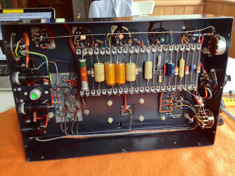
IIRC from the visit, the ones which blew are the wrapped capacitors. The mustard ones are all fine. The Hunts cap is on the other side (they sit on top) but the leads are centrally located and can't quite be seen from this picture.
Big J
"... only a very few individuals understand as yet that personal salvation is a contradiction in terms."
Edits: 02/27/15 02/27/15 02/27/15
I kind of thought so..The 4Uf cap you are speaking of is a filter cap.As long as the B+ is ok going into the choke which is 465vdc or a bit higher,that cap is fine.The caps that will cause the output tubes to run away are C7 and C8.Old caps like that tend to leak DC voltage on to the grid of the tubes causing the tubes to draw grid current and therefore start glowing cherry red.If you replace the power supply caps other than the 4uf which I'm pretty sure is ok, then change the coupling caps and change any out of tolerance resistors around the tubes,your tube runaway problem will disappear.
"If it measures good and sounds bad, it is bad; if it measures bad and sounds good, you have measured the wrong thing."
- Daniel R. von Recklinghausen
Edits: 02/27/15
I was told that the voltages are both higher - one around 480 and the other closer to 500V. I certainly have some more questions to ask about what is going on in the amps.
Question: could the EL34s themselves, cause instability if they are out of spec, somehow? Or is this unlikely?
Big J
"... only a very few individuals understand as yet that personal salvation is a contradiction in terms."
only the 500vdc one is a problem. When these amps were made,the typical AC line input voltage was about 5% to 10% lower many cases than it is today.For instance,your AC main voltage is 230vac correct? At the time the amps were made the line AC voltage was probably around 217vac to 220vac so the additional 10vac to 13vac would explain the higher DC voltage of 480vdc.Many amps have a line voltage setting on them for this very reason but from the schematic I looked at your amps do not.
This is not much of a problem with the amp reading 480vdc because it is well within tolerance of less than 5%.
You asked if the EL34s were bad or in a weakened state,would this raise the voltage? Absolutely because if the tubes don't pull enough current,the voltage will read much higher.
Swap the tubes around in the amps to see if the voltage problem follows to the other amp.If it stays the same,you then need to find out why and that is usually because cathode resistors that have gone up in value.
I have also seen different brand GZ34 rectifier tubes vary the voltage out by 15vdc to 20vdc but it's rare.
"If it measures good and sounds bad, it is bad; if it measures bad and sounds good, you have measured the wrong thing."
- Daniel R. von Recklinghausen
Edits: 02/28/15
Got that. In the case of the RFTs, the problem follows the two tubes. Substituting 2 Svetlanas cured the issue so this would seem to lend support to the idea that the tubes are not behaving normally .
Yes, 230V here in Auckland, though it can vary.
Big J
"... only a very few individuals understand as yet that personal salvation is a contradiction in terms."
Would you consider something more modern than PIO? If so, the current rage is the "DC link" cap. Metalized polypropylene and various values @ 600-630VDC and greatet. Avail from the usual sources.
The PIO preference is in deference to the original design. Not sure what a DC-link cap is? My bigger concern is how much it may change the sound...?
Big J
"... only a very few individuals understand as yet that personal salvation is a contradiction in terms."
You want to stick with the paper in oil to at least maintain some semblance of the original sonic structure.There are very good caps as well in other types,but I think this one here is going to be what you want and it has the same shape as your original from what I can see.
"If it measures good and sounds bad, it is bad; if it measures bad and sounds good, you have measured the wrong thing."
- Daniel R. von Recklinghausen
I have used those Russian caps in the link and generally like them better than most plastic caps out there even some expensive plastic caps.
I think they even give some of the newer paper caps like the fairly pricey Jensen PIO caps a run for the money and the cost is so reasonable on the Russian caps you will be very pleased at the price/performance ratio.
Looking at the rest of your amp I would say those Russian caps would not be out of place sound wise.
Just make sure they are going to fit as the square form is a little weird.
AM
I agree wholeheartedly with everything you said. Since I posted that,he posted the schematic and once he did that,you can see the 4uf was the charging cap in the power supply.I think the one he has in the amp is fine.The way he talks is like he may have a tube glowing problem and in that case the coupling caps,C7 and C8 are suspect.
"If it measures good and sounds bad, it is bad; if it measures bad and sounds good, you have measured the wrong thing."
- Daniel R. von Recklinghausen
Can be had at a 3.9uF value. What do you think?

Big J
"... only a very few individuals understand as yet that personal salvation is a contradiction in terms."
Post a Followup:
| FAQ |
Post a Message! |
Forgot Password? |
|
||||||||||||||
|
||||||||||||||
This post is made possible by the generous support of people like you and our sponsors: