 |
Audio Asylum Thread Printer Get a view of an entire thread on one page |
For Sale Ads |
|
|
Audio Asylum Thread Printer Get a view of an entire thread on one page |
For Sale Ads |
69.23.232.228
In Reply to: RE: Anybody Using 5R4's in Cary Sli-80? posted by Blackdog on December 29, 2015 at 13:48:43
which recommended the 5AR4 over the 5U4 and 5R4.
But I wonder how it (5AR4) behaves with respect to high cap. value?
Follow Ups:

There are plenty of 5AR4 data sheets on line. I've linked to the Amperex below, which shows the maximum value of the first cap at 60 �F. Keep in mind that that is a maximum, and lower values put less stress on the 5AR4, especially if you're using current production.
"You won't come back from Fletcher-Munson curve"-Jan and Dean
That 60uf is assuming there is the proper minimum series resistance (winding DCR or added series resistors) of from 75 to 200 ohms (depending on application) for each half of the power transformer's secondary winding.With lower values (than called for) of limiting resistance in place, the max. allowable capacitance goes down.
With a critical inductance input choke there is no resistance requirement because there would be no current peaking.

Tre'
Have Fun and Enjoy the Music
"Still Working the Problem"
Edits: 12/30/15 12/30/15
... that say there is a 1200 μF cap. coming right out of the rectifier in the Sli-80. If 60 is the max for a 5AR, then MAN, what does that say?! I must be missing something.
1200uF as input cap will quickly destroy even the great old stock 5AR4s. Take note that even the reasonable value of 60uF assumes a specific minimum plate supply impedance. This requirement is frequently overlooked or at least misunderstood.

The dark-/light- blue caps. appear to be the ones following the rectifiers, and they read 47uF (a stock photo). Have no idea where they got the 1200 value.
The large cans that are clamp mounted are the 1200 uf caps. You can see the terminal end of them at the bottom left and bottom right of the picture. They stick up a good ways above the top chassis deck, and are 2" in diameter. The black caps are Solens, the dark blue axial caps are Nichicon. All are stock, they are from the factory.
Could I ask - what are you trying to accomplish with the change to a 5R4? If you can let me know I may be able to be some help. Honestly, this power supply definitely needs some help!
I believe Michael Samra has posted about replacing these monster �F caps Cary used with 40 to 60 �F motor run caps. The chassis holes and clamps are already in place, so getting them to fit should be easy.
"You won't come back from Fletcher-Munson curve"-Jan and Dean
I developed a complete rework of the power supply back then, Mike was a contributor, yes. It got an outstanding review and at one time I offered to do one for just the cost of the parts (free labor) but I had no takers. So I pretty much forgot about it until this thread popped up...
I'd have given credit where credit was due, had I known it was something you developed. Either that wasn't mentioned in the posts I read, or I'd forgotten about it.
"You won't come back from Fletcher-Munson curve"-Jan and Dean
Not a problem at all, no apology required! Mike was definitely a part of it and a significant one at that.
BTW, here's what the owner of the amp said about it:
"Jim,
The impact of the PS upgrades on the Cary is really unbelievable! The amp is clearly making a fair bit more power and just does everything very noticeably better - resolution, low-end & soundstage... You might consider doing a kit for this amp - there are a fair number of them out there now and this is *huge* upgrade. All the stuff fits well."
I may be able to do one for somebody in a few months, January to March is my busiest time so it'd be after that. I still would like to get my hands on one at some point.
"You won't come back from Fletcher-Munson curve"-Jan and Dean
5R4GYS; hear very good things about them, particular their midrange.
But if the Sli-80 is hard on rectifiers, I am now thinking twice about it.
Also, does it matter (as far as being hard on rectifiers ) that those 1200 uF caps are directly attached to the transformers (I think), and the ones directly attached to the rectifier sockets are 47 uF?
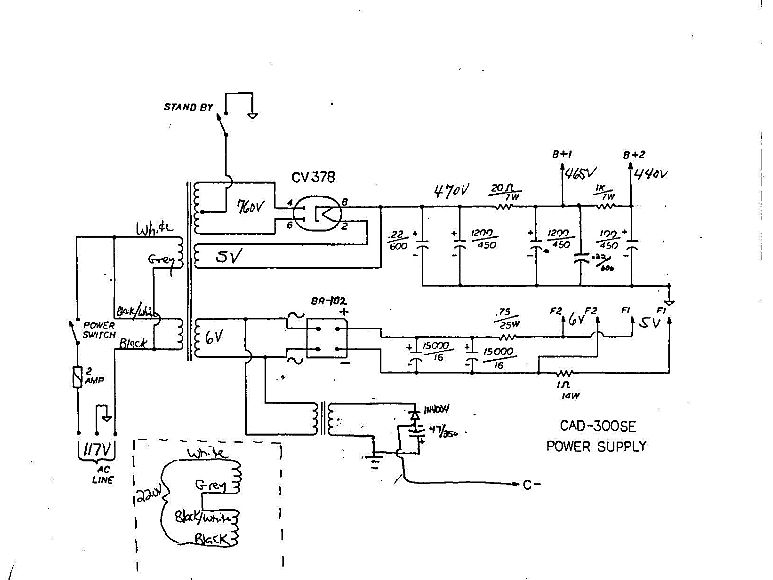
Does it look like your amp's PSU? This one looks like 22mfd in first stage, followed by two 1200mfd. No choke. And a GZ37 rectifier. Total cap would still be over recommended GZ34/5AR4 values. I think...
Their website does mention 1200mfd caps in the main filter supply.
It looks like the first cap is 1200uF @ 450V (notice the B+ is 470V!) bypassed by a .22uF cap. The rectifier is a CV378/GZ37/53KU. Max input cap for the CV378/GZ37/53KU is not given in the data sheet I could find, but in "typical application" it suggests 4uF.
...is suggested for CV378 but if you compare max repetitive peak current to that specified for 5AR4 you'll find the values identical. Since input cap value along with plate supply impedance are the significant determinants of max peak current, it's pretty safe to conclude that max cap value for CV378 is identical to that of 5AR4 at 60uF under identical conditions. Either way, 1200uF as called out in the schematic is grossly excessive...assuming of course that plate supply impedance is conventional.
I agree that in theory the GZ34 and GZ37 should be roughly equivalent. In practice however I have found the GZ37 to be much more robust. I had a pair of Quicksilver KT88s in the 1980s (they had a first cap of several hundred microfarads) and the GE GZ34s that were easily available at that time for a nominal cost would only last a few months. I eventually changed to the GZ37 that were $16 from Ned Carlsen and never had a failure with them.
Post a Followup:
| FAQ |
Post a Message! |
Forgot Password? |
|
||||||||||||||
|
||||||||||||||
This post is made possible by the generous support of people like you and our sponsors:

