 |
Audio Asylum Thread Printer Get a view of an entire thread on one page |
For Sale Ads |
|
|
Audio Asylum Thread Printer Get a view of an entire thread on one page |
For Sale Ads |
75.140.82.42
In Reply to: RE: Microphonics posted by kylealers@gmail.com on August 03, 2015 at 07:05:24
A little microphony is normal. You can try tightening those socket tangs with a dental probe. Be sure unit is OFF and main caps are discharged, first. Caig Deoxit (GN-5) will also help with the contact surfaces.
Follow Ups:
What difference will changing the resistors running parallel to the bypass caps make I've seen some schematics using 1.5k mine is at 2.2k and some have 4.7k this is confuzing me a bit would changing these resistors make a big difference to the sound?
Those resistors set the idle bias point. I would not change them, unless you have a known idle parameter that you are heading toward. Which usually depends on the specific tube type and its role in the circuitry.
IOW... you need to calculate the idle current you wish, depending on tube type, the function in the circuit, and plate voltages.

Doesn't it seem on this schematic using 12ax7's that on the first gain stage pin 6 and pin 8 are the wrong way around? Because on all the 12ax7pin outs I have pin 6 is the plate and pin 8 the cathode on here it says its the other way around
But, if the thing is working... The socket wiring must are been modified, as 5670 has different pin-outs versus the 12AX7.
I'm starting over using 12ax7's also using a 230v isolation transformer that is the 12ax7 schematic but I've seen there is a fault on the schematic at v1b the cathode and plate are the wrong way around according to the pin out of a 12ax7
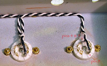
Dunno for sure. You definitely need to rewire the heaters into parallel connections. Pin 4 & 5 to one heater line. Pin 9 to the other. Both lines should be twisted.
The 5670 uses 6.3VAC, in series wiring. 12AX7, 12.6VAC in parallel. Both use 6.3VAC heater tap.
I'm basically running one 12ax7 in the tone stack and a 5670 for the effects loop I think the 5670 can run 12v in series aswell I used to run both of them in series from a 12v tranny now just to figure out how to run a 12ax7 and a 5670 in series on 12v so basically I need to run both tubes at 6.3 v In series on the 12ax7 pin 4 and 5 together and pin 9 going out to pin 1 of the 5670 and pin 9 of the 5670 going to heaters earth?
Edits: 08/08/15
Just wire the heater lines to #1 and #9 --- in the 5670. And you are using 6.3VAC (of a 6.3VAC PT heater tap).
Wiring the 12AX7, #4 & #5 (connected together) to one line and the other to #9 = 12.6 VAC in parallel.
All off the same heater taps.

I don't have a 6.3v for the heaters I only have 12v that's why I need to have them in series. The 5670 has no centre tap it can only use 6.3v in series or parallel the 12ax7 can use either 12v or 6v but om not shure if you can use it at 6V in series
This picture is the wiring for the 12ax7 in 12v and 6v
You need a 6.3VAC source for the 5670 tubes. AFAIK, they cannot be wired in parallel like the 12AX7. Are you absolutely sure about your heater voltage? Better measure it. Pretty sure it is 6.3VAC. If it taps off the main PT.
Oke so I have to get myself a tranny that has 6.3v out the isolation transformer I have is only a 230VAC transformer no 6.3VAC out. Wich will be the best for running my 5670 and 12ax7? I can get 2x6 VAC , 6-0-6 VAC or 1x6VAC.....oh and I want to run the heaters in regulated DC I have the schematic for it but do I need to build 2 identical rectifiers to run each tube on its own dc circuit so I guess a 2x6VAC tranny will be the best then?
Edits: 08/09/15
What did you use to heat the 5670 tubes, previously? That should be good enough. The 6.3VAC supplying the 5670, at that time, should be adequate for the 12AX7. As the 12AX7 require less amps to run their heaters.
Edits: 08/10/15

They were in series I used a 12v DC power supply

I had the 5670's wired in series from a 12v dc power supply

You can use the current heater source. You hook ONE heater line to both pins 4 & 5 (soldered together). The other heater line to pin 9. Voil�! Two 6.3VAC lines in parallel = 12.6VAC.
If you keep the 5670 in other positions, just leave the wiring as is, for those tubes.
Wiring in parallel, for the 12AX7 heater. Using a 6.3VAC source:
-----
I'm running them in dc tho So basically the same as on the picture accept the 5670 should be at pin 1and 9 not 4,5 and 9 and this is from 6.3v DC?
Edits: 08/10/15
That's the thing I'm using 1x12ax7 and 1x5670 so I have to run them both in parallel at 6.3v so the best tranny to get would be something that has 2x6.3vac
I kinda see what the problem is now. Parallel has two meanings here. Within each 12AX7, there are two heaters --- which need to be wired in parallel with each other. So that the two 6.3VAC heater line taps = 12.6VAC, within that tube. And each tube should be in parallel with each other. That is, the 5670 and 12AX7 lines run parallel to each other. Not in series. That's how your lines should be.
Wire the 5670 to #1 and #9. Then, run two lines from the 5670 to pins 4&5 and pin #9 of the 12AX7. The heaters of all tube should be in parallel with each other. That is, if you pull one tube, the others will still work. Don't have the tube heaters in series with each other (you pull one tube and the others downstream stop working).
This way you can use 6.3VAC and 12.6VAC heater tubes from the same 6.3VAC PT tap.
From the diagram, you can see how each 6L6GC heater line and the 12AX7 heaters are wired --- off the same 6.3VAC tap. Thus, one pair of 6.3VAC or 6.3VDC taps is all you need to run your unit's heaters.
-----
BTW... are you still able to see these posts ok? This has to be one of the longest continuous thread off a single post I've ever seen.
8^)
Looks like we've cracked that code lol...I'm going today to get a 6.3v tranny. Bought the components yesterday to build a decent 6.3VDC power supply. It possibly is the longest thread in existence but you have been of so much help wouldn't have gotten nearly this far without it I went from basically no knowledge of electronics to being able to build a bass pre amp from scratch in about 2 months all with your help of course lol so thank you so much man. When this pre amp is done now all the kinks ironed out the next project will be building a 100w tube power amp I'm using a solid state power amp at the moment and I don't like the sound of micro chips hahahaha
An Ampeg B15N Portaflex clone would be most delicious. You can mike it to the house system for more volume.
For sheer power, a redone Ampeg SVT or better yet... Fender 400PS would really be neat. Complex puppy... but 400+ tube watts are beyond loud.
I'm thinking anything in the 100w range would by sufficient in driving my 400w 4x10 genz benz cab building a svt power amp section is a bit way out of my hands I'm thinking any generic power amp running off 4x6L6's would do?
These are essentially Fender Twin Reverb head amps. Plenty of power for a medium to large (church sized) room.
A couple guys whose DS I've restored use them to amplify their bass for gigs. Stock voicing.
Ah I would've loved one of those but you see finding those locally on my side of the pond is completely impossible and if I find one its gona be $1500+ in whatever condition it might be a while back I had the chance to buy a 135 bassman with the 2x15cab just didn't have the $1600 back then. Finding one from your side of the pond meaning first world heaven hahaha is easy but shipping it to south africa is basically going to cost double the price of the amp + the price of the amp that's why I'm building my own its a bit more affordable
Maybe the Marshall 100Watt Super Bass clone?
I am a very big marshall fan both my guitarists play jcm 900's I would love a british style power section can you maybe post any schematics?
Schemo link.
What's the difference between a inline rectifier bridge and a normal one? Juts noticed something
Just two different ways to draw the schematic for the same thing.

Is it important if my heater transformer doesn't have a centre tap to make a artificial centre tap?
If you are going to wrap the two leads to lower hum (only works if current is AC) --- then it is important to "center" the wave form. That is what using 100-ohm or 220-ohm resistors does.
However, if you convert the heater taps to DC, you do should not do this.

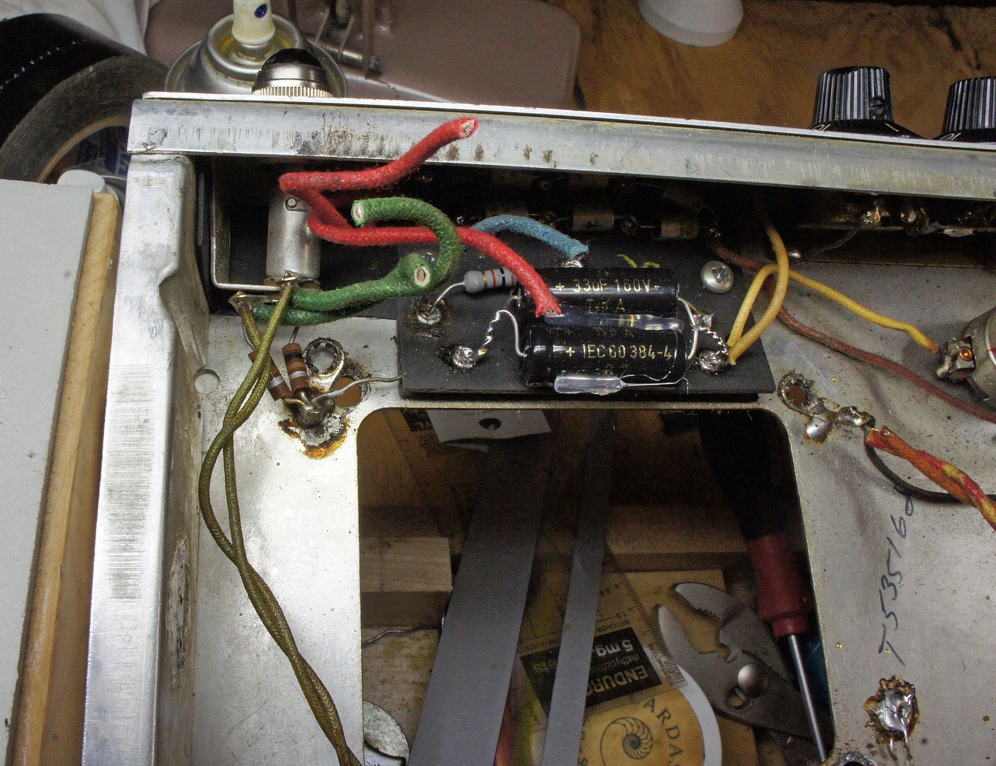
Awesome thanx for the advice man my heater tranny is 6.3VAC 1,42amps it would be better using 220ohm than 100ohm? Here is some pics of the pre amp so far.
I like 100-ohm resistors. 1/2 watt, 5 or 10% is fine.
Hey! What kinda beer? I like Dos Equiis, while soldering.
8^)
That's carling black label its a local beer here in south africa everybody drinks it here very cheap but also one of the best
Beer always makes my fingers "looser" and the ears "better."
8^)
Where will be best to earth this artificial centre tap?
Tie one end of the two resistors together. Solder this pigtail to a lug which is bolted to the chassis. You can do this at the power lamp (which is the first to get the heater line tap from the PT, in most Fender amps). Or anywhere close to the tap point off the PT.
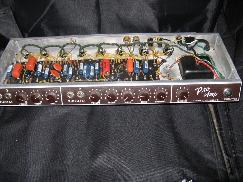
See the two 100-ohm resistors tied to ground, after the power lamp in this Super Reverb? The clipped, heavy green lines come from the PT.
I've downloaded PSU designer and I want tweak this power supply a bit how do I calculate the load resistance? and how do I know what resistance a capacitor holds?
There are ways to improve the PSU, without re-designing the unit from scratch. Is this mod going into the bass pre-amp or the main bass DIY amp you wish to construct?
Better diodes, better filter caps, stable rail resistors are all good starting points.
So I decided to run my heaters in ac just for now I will hear how much the noise is. When my heater transformer doesn't have a centre tap is it important to make a artificial centre tap? Like in the pic?
Yes, artificial center tap is the way to go... if no actual CT.
Wrap the two heater lines together and with the two resistors making an artificial CT --- you'd be surprised how quiet the line is. Keep the heat lines above the socket surface and away from signal lines.
Like this:

This is the diagram exactly like I have it now any tips or hints before I test?
You sure you want to run the 12AX7 after the 5670? I thought you wanted one line with no TS and the other one with a TS. I think the gain stage with one 12AX7 as input tube is sufficient for your needs.
Just run another input into the 68k-ohm resistor before the first half of the 12AX7. OUT #1 from the 5670 to the bass amp input --- not connected to the 12AX7. OUTPUT #2, into a separate input of the bass amp.
Have each input jack ground out, when not in use. Then, plug the bass guitar into whichever gain stage that you want (no stack or tone stack).
I pushed the thread up to the top, with new thread. If that helps you.
that 85-100 --- reliable, road-worthy --- watts are about the limit of most tube designs. Esp in the bass range.
Consider the Ampeg B15N design. One of the most used bass amps, in recording studio history. Miking it to the house system is a viable solution. You get reliable mega 100's of watt of power, with the silky smooth output tube OD of the 6L6GC tubes.
-----
Pre-made DIY kit is the way to go. Pure scratch build requires a good knowledge of tone controls --- as we know, 8^), feedback, instability issues, etc.

If you haven't heard a good 85-100 Watt tube amp, you'll be VERY surprised how much louder they sound next to comparable solid-state units.I have a blackface Twin Reverb loaded with two JBL K120 speakers. It is so loud, I can get the 2X4 wood beams in my house to start vibrating --- easily, at volume of 5 out of 10. And that's with a Les Paul guitar. Not even a bass guitar.
Edits: 08/11/15

Very juicy tones.
Post a Followup:
| FAQ |
Post a Message! |
Forgot Password? |
|
||||||||||||||
|
||||||||||||||
This post is made possible by the generous support of people like you and our sponsors:


