 |
Audio Asylum Thread Printer Get a view of an entire thread on one page |
For Sale Ads |
|
|
Audio Asylum Thread Printer Get a view of an entire thread on one page |
For Sale Ads |
71.29.35.128
Got rid of almost all of the hum in the 26/26/845 by going to dc filaments on the 845. I still have a tiny bit left though that is just barely audible from my listening position. I noticed that it does not change with an increase in volume level, just a steady amount. Is that likely to be from the PSU? I had better check it again on psud2 for ripple. I don't think it is coming from the 26's as the hum pots seem able to cancel it out completely there.
Follow Ups:
Should have thought of this a long time ago.... I hooked my cd player directly to the new amp (took the preamp out of the picture) and low and behold the hum went much lower. That means I need to dive into my preamp because it isn't as quiet as I thought it was. I have dc on the 26 filaments of the preamp, but I might need to take another look at my filtering for the dc.
At least I know what the main problem is now. I will still have to do a little tweaking on the 845 too, but I will plus up the preamp first. Thanks for all the help folks, I appreciate it.
Edits: 09/14/16
A spectrum analyzer will show 60 cycle (AC hum) and 120 cycle (PS ripple) in relation to a typical test signal ( usually a 1KHz sine ).
I playing around with my RH test amp last night and noted that the 60 cycle hum was down about 75dB or so from the test signal.
120 cycle ripple would go down by adding more PS filtering.
It is easier to see if a circuit change is meaningful or not with something visual to look at like a graph in real time.
That would be great if I had one. Expensive piece of equipment I believe.
If you have a PC and a decent 192KHz soundcard, you have a basic audio measurement system.
There are freeware programs like ARTA or others online.
Search the archived posts for what others have already done.
.
Have Fun and Enjoy the Music
"Still Working the Problem"
I think for now I will just use my on line tone generator to determine if it is 60 or 120. Much simpler and I already have everything I need. Thanks just he same guys.
A DC filament supply filter that is cap input will have some nasty looking ripple that sometimes can be heard even if the ripple level is low.A choke input supply filter for the DC filament supply will have only sine wave ripple that is not as easily heard.
Because the current draw is high and the voltage is low the needed Henry value of the input choke is low and won't break the bank.
Calculation for critical inductance Henry value for a input choke.
((voltage/current in amps) + DCR of choke) / 1000 = choke value in Henry
For my 300b I use the CH-2. It's 70mHy and that's overkill.
For a 26 critical inductance is going to be about 5mHy or something like that. Of course the supply voltage will have to be high to start with.
Tre'
Have Fun and Enjoy the Music
"Still Working the Problem"
Edits: 09/14/16
Thanks Tre'. I will keep that in mind as i look for a solution.
Either I am hearing little hums in my head or the hum comes and goes as it likes. Sometimes it there and sometimes I can't seem to hear it, or at least it doesn't seem as loud. Don't send for the men in the white coats just yet, I think I may need to clean up my act so to speak. In other words get rid of all that extra wire in the form of clip leads. I may have to build one channel on a plywood chassis so I can get the lead dress right, etc, etc.
Edits: 09/13/16
DC on your AC mains? I had an issue with a tube amp that did that and it was due to DC on the mains. I had .6vdc on mains. I bought a Humdinger and it took care of that hum.Sometimes the DC can vary on the mains so can cause what your hearing.
also make sure your filament wire are twisted tightly together and running against the chassis. This can reduce or eliminate hum.
Another thing is make sure you are using shielded cables from power to interconnects. When using my table I kept getting hum that would be almost gone but come back again a little louder and it was due to my braided but unshielded cables. Put shielding on them, all gone.
Sorry for not being able to help sooner. I have been finishing up the build of my Latino VTA-120 which had a filament issue that I tracked down and fixed. Now that amp is dead quiet!
Edits: 09/13/16
I will check the mains for DC, but all the others have be covered. Thanks.

Somebody ought to outlaw hum. Man what a pain in the patootie! I need a check on my methods here to make sure I have got this right. Trying to start at the top so i eliminate the hum from my preamp before I try getting rid of it on the amp.
To measure it on the preamp I turned it on but had no inputs on. I then measured across the out put rca cable and got about 10-12 mvac. Is that the correct way to measure it> I also reran the psu on ducan amps to make sure I had that right. Using the schem above I came up with about 2 mvac of ripple. If some one who uses psud2 a lot could check that I would appreciate it.
On the ripple, I get 3.5mv AC peak to peak. 3.5 / 2 = 1.75 mv peak X .707 = 1.237mvac rms.I have questions.
1. Where did you get a 10Hy choke with 30 ohms DCR?
2. The sim shows an output voltage of 285vdc into a load resistance of 5k ohms. That would be 57ma of current. Does your preamp circuit draw 57ma. of current?
3. Is there a volume control before the preamp tube(s) and was it turned all the way down when you made your measurement?
BTW The ripple on the audio output of the preamp will not be at the same level as the ripple coming out of the power supply.
Tre'
Have Fun and Enjoy the Music
"Still Working the Problem"
Edits: 09/13/16 09/13/16 09/13/16 09/13/16
Opps, just checked the data sheet and that should be 155 ohms for the 10H and 105 for the 5H.
The 5k ohms is the bleeder resistor that is actual on the psu just as drawn. I still haven't figured out how to calculate the actual load; more delving into the instructions needed I guess. The volume control was all the way off. and I shorted the input rca just to be sure.
The ripple out of the audio out of the preamp has been amplified by the preamp right? What should i b e shooting for there, less than 5mvac like an amp or less?
I think you meant 1.237 mvac, not vac right? If that is the case that is close enough as I was just eyeballing it from the graph.
mvac, yes. Post corrected.
I'm not sure what to shoot for using a DHT in a preamp. With IDHT in a preamp, I over build the outboard power supply and outboard DC heater supply and get no hum at the output of the preamp.
But that is going to be different with a 26. Or maybe not if you did a really good DC filament supply.
Tre'
Have Fun and Enjoy the Music
"Still Working the Problem"
mt
Yes, that is what I found on the 845 amp. This morning I was measuring the total ripple including the preamp and found I had more ripple on the preamp than I thought I had.
You have many possible sources of hum.
1. B+ supply in preamp. 120Hz
2. Filament supply in preamp. 60Hz if it's AC, 120Hz if it's DC.
3. B+ supply in power amp. 120Hz
4. Filament supplies for input and driver stages. 60Hz if they're AC, 120Hz if they're DC
5. Filament supply for the 845. 60Hz if it's AC, 120Hz if it's DC
Tre'
Have Fun and Enjoy the Music
"Still Working the Problem"
5. Filament supply for the 845. 60Hz if it's AC
That's not correct, at least not in tubes with large filament structures like the 211 and 845. Those tubes also generate considerable harmonic energy at 120 Hz. I first discovered this when I built a circuit attempting to null the 60 Hz in a 211 amp. It worked, but there was still too much 120 Hz energy. I eventually discarded the whole idea. It seemed futile to try to duplicate the entire harmonic signature being created by the filament for purposes of nulling. That was when I moved to DC, and later to ultrasonic heaters.
--------------------------
Buy Chinese. Bury freedom.
"Those tubes also generate considerable harmonic energy at 120 Hz."
You are right. But he WILL be able to null the 60Hz. There's not much he can do about the 120Hz harmonic. I think he already went with DC for the 845 so it's moot.
I just thought if he had a list of all the possible sources of hum it might help him track some of them down.
Tre'
Have Fun and Enjoy the Music
"Still Working the Problem"
What set up did you use for dc?
I tried several, including a simple bridge/filter, a bridge/filter/regulator (linear), and a switcher. Switchers have a potential advantage insofar as their high frequency step-down transformers isolate the DC from common-mode noise on the AC line. It was my experience in every case, however, that DC heating of the 211 sounded dry and lifeless compared to AC, regardless of how the DC was derived. That was the impetus behind my search for a practical (i.e. inexpensive) method of ultrasonic heating.
--------------------------
Buy Chinese. Bury freedom.
That's been my experience too, although the 845 doesn't seem to lose as much. Did you ever get a finished version of the ultrasonic heater? If so did you or could you you post the design?
Vinnie, I never did finalize a sine wave version, but I'll tackle that eventually. Meanwhile, the square wave doesn't seem to create any audible issues. If you search the forum and read up on the work that's been done in this area, I think you'll have enough to duplicate my efforts. One thing to remember about these supplies is that everything ahead of the 12V output (step down) transformer is attached in one way or another to the AC mains. If you're inclined to do a lot of experimentation, a small isolation transformer would be a great investment.
--------------------------
Buy Chinese. Bury freedom.
Thanks TK, I will see what I can find.
Triode_Kingdom did all the leg work on this using a simple 12v supply off Ebay.
You can no longer find the exact supply but one similar. I did this last year using TK methods and it worked perfect!
Triode_Kingdom Supply Link
--------------------This is the content and basic instructions--------------------
The first thing you have to do is pop the top off the box so you can get at the circuitry. Removing the PC board is a simple matter, once the box is open. Next, ferret out the connections at the four rectifier diodes and determine which leads represent the + and - output. You will then need to add a capacitor across those points, approximately 450uF / 200VDC.
Now, the next time you plug in the supply, it won't work. You'll discover that a small resistor (0.1 or maybe 1 ohm) located at the edge of the board has opened. That occurs because this is a fusible resistor, and the surge created by charging the new capacitor is too much. Replace the resistor with a 5 ohm, 5-10 watt part.
The next issue to deal with is the output frequency. 25 KHz is too low for audio work. The board contains a small toroidal transformer, and that needs to be modified. Remove the transformer from the board and you'll see it has two separate windings, about five or six turns each. Cut one end of each winding loose and unwrap all but one turn of each. Resolder the loose end of each winding. The next time you fire up the supply, it will output a 12V squarewave at approximately 60-65 KHz.
The last thing you'll need to do to use the supply is to add a dropping resistor at its output. The supply outputs 12V, so for a 211 drawing 3.25A, you'll need approximately 0.6 ohms. I use two 0.33 ohm resistors, one in each leg of the filament. I should add that I much prefer this approach to any sort of constant voltage regulation, or to modifying the turns ratio of the power supply's output transformer (not the same transformer mentioned previously). At the very least, the dropping resistors help to mediate the inrush current when the tube is cold. I mount the resistors directly to the filament posts of the 211 socket.
To use the supply, you'll need to mount the PS circuit board in a larger case. It won't fit in the original plastic container with the addition of the larger resistor and the filter cap. Make sure the PC board is well insulated from anything metal. The input circuit (oscillator transistors, diodes, filter cap, and toroid) are electrically connected to the AC line. In fact, only the two output leads (driven by the conventional output transformer) are isolated.
The Ebay link is the supply I used, just search for "12v halogen supply

This morning I measured the ac on just the 10 volts of dc for the 845 filament with the preamp disconnected from the 845 amp. It was only 2 mvac. This tells me I am ok with the dc filter I am using on the 845. However, when I hooked the preamp back up it jumped up 19 mvac. I think my problem has been the preamp all along, so I am going to concentrate on getting that down below 5 mvac and see what that does for me.
What is it that shows up as ripple at the speaker terminals that you measure? That is only AC isn't it?
Edits: 09/13/16
Vinnie
When you did AC filaments on the 845,were you using a separate filament transformer or at least an independent filament winding on the power trafo? If you don't,you will get hum.
"For every complex problem there is an answer that is clear, simple, and wrong" H. L. Mencken
I am just doing one channel now, so the 845 has a nice little 10v/8A filament trans all to itself.
Edits: 09/12/16
Perfect.That's what you want.
"For every complex problem there is an answer that is clear, simple, and wrong" H. L. Mencken
Thanks for all the suggestions folks, it allowed me to find the problem. It's the filament supply on the 26's, which still have AC on them.
I found a neat little tool called the "on line tone generator" on the net. It lets you generate a steady tone and to generate multiples of that tone with a mouse click. It was real easy to flip back and forth between 60 and 120 and hear the difference. That was enough to tell me my hum was 60 hz and was therefore coming from a filament supply. I went back to the first 26 and tweaked the hum pot very carefully until I got it as low as I could by ear, and then I checked it again with the dvm and it was down to 20mV. That's a big decrease from 110 I got the first time, so I think if I put in a 10 turn pot on each 26 and adjust them by watching the dvm to get the lowest reading on each I just might get there. I will report back after I try it.
Edits: 09/12/16 09/12/16 09/13/16
I admire how you're really digging in and starting to understand this stuff.
Keep it up Vinnie!
In the long run you'll save yourself a lot of head scratching.
Tre'
Have Fun and Enjoy the Music
"Still Working the Problem"
Even a blind pig finds an acorn once in a while, but the help you and the rest of the folks have given me for so long has really helped. It is a nice feeling when I can actually see how some of this fits together. I don't think I will ever be a whiz kid on the theory, but some of the nuts and bolts stuff just might sink in. Thanks!
Edits: 09/12/16
Scratching my head again. I ran my psu through psud2 and it shows virtually no ripple with the clclc filter I am using. First cap is 2uf then 8h, 47uf, 8h, 47uf. But when I measure it at the amp terminals I get 110 mV AC.
Guess I had better find out how to use the scope to see if it is 60 or 120 hz as that would help me by knowing where it is coming from for sure.
My guess, is if you are getting AC downstream from the rectifier... it's 120Hz.
You have a guitar? 60Hz = lower than a plucked open top string (low E, standard tuning).
120Hz = approximate open A-string (next string over from low E).
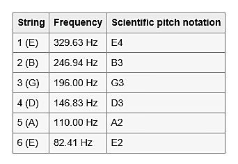
60hz hum = filament supply
120hz hum = B+ supply.
Also are the filament lines balanced? if not this could cause hum. Routing of filament wires could be an issue.
How do you tell if it is 60 or 120? I have a scope and a dvm to work with. If by balanced you mean hum pots, yes.
Edits: 09/12/16
yes, I meant a balance or hum pot.
You can look at how long one complete cycle takes. Your scope displays in time (most likely), so count the distance from start to end of cycle and invert to get hertz. 120 hz is 0.0083 (8 ms) seconds, for example. So if you set horizontal to, say 5 ms/div, then you should count one whole square and 3 additional tenths to = 8ms if it is 120hz hum.
That's another tool for the tool box. Thanks!
Being a triode, 10vac is difficult to tame for most of us.
Have you tried Rod Colemans boards yet?
Also, Triode kingdom has a cool trick using a 12v low voltage supply off EBay using AC but above the range of hearing (ultrasonic). Works great on the 845
I believe it's around 55khz. I bought a couple and successfully made the mods.
I might use them one day on my GM70 amp should I try some 211's.
I thought just going to dc on the filaments would be enough. Does it matter how you do it?
This works great with the 211 and 845
Best of both worlds, no hum and AC heated.
Better filter does matter!
Do you have a design for one?
Triode_Kingdom did all the leg work on this using a simple 12v supply off Ebay.
You can no longer find the exact supply but one similar. I did this last year using TK methods and it worked perfect!--------------------This is the content and basic instructions--------------------
The first thing you have to do is pop the top off the box so you can get at the circuitry. Removing the PC board is a simple matter, once the box is open. Next, ferret out the connections at the four rectifier diodes and determine which leads represent the + and - output. You will then need to add a capacitor across those points, approximately 450uF / 200VDC.
Now, the next time you plug in the supply, it won't work. You'll discover that a small resistor (0.1 or maybe 1 ohm) located at the edge of the board has opened. That occurs because this is a fusible resistor, and the surge created by charging the new capacitor is too much. Replace the resistor with a 5 ohm, 5-10 watt part.
The next issue to deal with is the output frequency. 25 KHz is too low for audio work. The board contains a small toroidal transformer, and that needs to be modified. Remove the transformer from the board and you'll see it has two separate windings, about five or six turns each. Cut one end of each winding loose and unwrap all but one turn of each. Resolder the loose end of each winding. The next time you fire up the supply, it will output a 12V squarewave at approximately 60-65 KHz.
The last thing you'll need to do to use the supply is to add a dropping resistor at its output. The supply outputs 12V, so for a 211 drawing 3.25A, you'll need approximately 0.6 ohms. I use two 0.33 ohm resistors, one in each leg of the filament. I should add that I much prefer this approach to any sort of constant voltage regulation, or to modifying the turns ratio of the power supply's output transformer (not the same transformer mentioned previously). At the very least, the dropping resistors help to mediate the inrush current when the tube is cold. I mount the resistors directly to the filament posts of the 211 socket.
To use the supply, you'll need to mount the PS circuit board in a larger case. It won't fit in the original plastic container with the addition of the larger resistor and the filter cap. Make sure the PC board is well insulated from anything metal. The input circuit (oscillator transistors, diodes, filter cap, and toroid) are electrically connected to the AC line. In fact, only the two output leads (driven by the conventional output transformer) are isolated.
The Ebay link is the supply I used, just search for "12v halogen supply
Edits: 09/15/16 09/15/16 09/15/16
May be you need better filtering (more caps) for the DC supply to the filament.Nope, you don't need Rod's boards for hum free DC. Low ripple DC should get rid of the hum completely. Check with the oscope if you have one, it may be in your B+ line if not in your filament line.
.
.
.Thou shall not stand where I type for I carry a bottle of Certified Audiophile Air and a Pure Silver Whip.
Edits: 09/11/16 09/11/16
With the inputs on RCA jack shorted, amp at idle, what is the mVAC on your amps speaker terminal Vinnie? We wanna see 5 mVAC or less.
Jeff
Post a Followup:
| FAQ |
Post a Message! |
Forgot Password? |
|
||||||||||||||
|
||||||||||||||
This post is made possible by the generous support of people like you and our sponsors:
