 |
Audio Asylum Thread Printer Get a view of an entire thread on one page |
For Sale Ads |
|
|
Audio Asylum Thread Printer Get a view of an entire thread on one page |
For Sale Ads |
63.246.183.223
In Reply to: RE: 845 Interstage A2 Question posted by danlaudionut on September 06, 2014 at 06:55:41
Wow, I can't believe the number of replies recommending that you screw up such a nice design with solid state devices. Anyway, if I understand your question correctly, the bias supply doesn't need to provide any additional current. 1.5 mA should be plenty. This is one advantage to using a transformer rather than a choke. In my amps (below), the bias supply has to provide all the current that flows through the driver. In yours, quiescent bias current will be no different than a cap-coupled Class A amp. Grid current needed by the 845 when it enters A2 will be supplied by the transformer. Just be certain the cold side is solidly decoupled (bypassed).
--------------------------
Buy Chinese. Bury freedom.
Follow Ups:
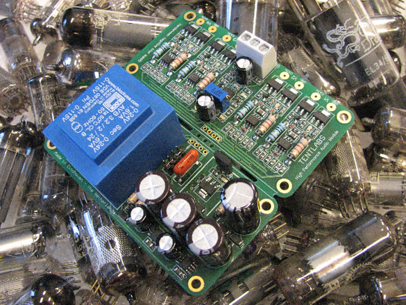
Boatload of solid state devices in a Tent Bias Supply.
The grid draws net current, since it only conducts on positive peaks. This current must come from the bias supply in the end. If the bias supply has a capacitor at the output, the underlying circuit only has to provide the average DC current at peak power.
To operate reliably in A2 you need to know what the grid current is, and how much power the grid can dissipate. As CB pointed out, the 845 is not specified for A2 operation so there is no manufacturer's data. Unless someone else has already done it and published it somewhere, you'd have to make your own measurements.
For the current (the original question) it's easiest to make a guess, build the amp, and measure the current. Monitor the bias voltage in case the bias power supply is overloaded - there is danger of runaway I think.
Hard to know what the grid power handling is. If the tube dies from a grid warping into the cathode, I guess you'll have a data point. :^)
Paul
Let's look at this another way ...
Let's say the A2 peak is +50V and the bias is -125V.
Those are the voltages across the IT secondary.
You are saying that positive current will be asked
of the already negative -125V bias supply.
That just doesn't seem right.
DanL

I would think the electrons flowing out of the grid would want to flow towards the supply that created the +50 volt condition at the grid and that isn't the bias supply.
What if, just for the sake of the conversation, we made the output tube cathode biased and connected the low side of the secondary of the interstage transformer to ground.
Now where are the electrons from the grid of the output tube going while the grid is positive WRT the cathode? (What is satisfying the grid current?)
Doesn't it somehow have to be the driver tube?
Tre'
Have Fun and Enjoy the Music
"Still Working the Problem"
> > the supply that created the +50 volt condition
Which is the Interstage.
> > Doesn't it somehow have to be the driver tube?
I would think it would be the transformer.
DanL
"I would think it would be the transformer."
Yes and that was my point.
The transformer is getting it from the driver tube.
Isn't the driver tube driving the primary, which drives the secondary and because of the inductance of the secondary isn't the secondary storing energy and that energy is what's supplying the grid current?
Tre'
Have Fun and Enjoy the Music
"Still Working the Problem"
Those grid electrons (in the case of cathode resistor bias and a grounded IT secondary) are going to ground, since the come out the other end of the secondary winding. The do not magically tunnel through the iron core to get to the copper wire of the primary!
Current loops are complete circles - in this case, electrons come from the PSU ground, go through the bias resistor/capacitor, to the cathode, from which they jump to the grid when it is positive enough to attract them, then to the IT secondary and back to ground - loop closed.
"Current loops are complete circles"
I understand that but doesn't the source of the grid voltage need to be part of that circle?
I was thinking that the source was the energy within the secondary, imparted there by the primary, imparted there by the driver tube.
I think in terms of the positive side of a power supply as being an electron "vacuum cleaner", needing to suck up electrons and any current (electron) flow caused by the presents of the positive side of a power supply (being connected to a circuit with the other end of that circuit connected to the negative side of the power supply) has to flow back through the positive side of the power supply to get to ground.
So, in this case, the power supply has (indirectly) energized the secondary of the IT and the electrons DO find ground through the ground side of the IT but the energy is "supplied" ultimately by the driver tube not a bias supply that's happens to be between the ground side of the IT and ground.
The grid current flows through the bias supply, but it's not sourced from the bias supply?
Paul, I realize that the above probably reads like a jumbled mess to you.
I only hope you can decipher it well enough to see where my thinking is wrong and teach me something.
Thanks.
Tre'
Have Fun and Enjoy the Music
"Still Working the Problem"
The "source is, as you said, the IT. It is approximately a voltage source, so at any instant it's like a battery. When the signal is at a +200v peak, and the bias is -150v, then the grid is held positive to the cathode by +50v, causing the grid current.
The current in the secondary does not have the same electrons as the current in the primary, even though through the magic of electromagnetism the currents and voltages mirror each other.
That's what I thought.
The grid current is not being sourced by the bias supply but instead is being sinked through it?
If the total current (from and through) the bias supply is more than it's rated for Dan will have problems?
Tre'
Have Fun and Enjoy the Music
"Still Working the Problem"
"The grid current is not being sourced by the bias supply but instead is being sinked through it?"
Not necessarily. Here's another explanation, and I apologize if it's too simplistic. I'm just trying to lay out the whole concept from A to Z...
To set this up, the secondary of the IT swings voltage at its upper terminal referenced to ground. In order to do that, its lower terminal must be held as closely to AC ground as possible. We can't actually ground it, because that would short the negative bias needed by the grid. So, a bypass capacitor is connected from the bottom terminal to ground.
Here's what happens when this arrangement is driven in A2...
When the audio signal at the upper terminal of the transformer swings more positive than the grid bias, electrons are drawn from the grid. They flow down through the transformer secondary winding toward AC ground. The electrons are pulsed at an audio frequency, because in this design, the grid only draws current on positive-going peaks. The current pulses flow out of the secondary at the bottom terminal and through the bypass capacitor to ground. That's the complete path for grid current if the bias supply is isolated with a series rectifying diode, as most are. 10 ma of grid current creates exactly 10mA of current through the capacitor.
The problem with this arrangement is that the pulsed electrons entering the capacitor cause the average DC potential on the capacitor to become more negative. In other words, when grid current is drawn, the capacitor immediately becomes more negative than the bias supply that charged it up in the first place. If there is no DC path to ground at this point in the circuit, the capacitor will continue to charge as long as grid current is drawn. It won't stop until the capacitor and the grid become so negative that grid current no longer flows.
What's needed is a way to prevent the DC voltage on the bypass cap from increasing. That can be done in several ways, including a Zener of exactly the right voltage (as Paul noted), a bias supply that drains off the excess voltage by sinking it to ground, or even a resistor. If the purpose of the amplifier's A2 capability is only to handle musical peaks without clipping, and if those peaks push it into A2 only occasionally, the resistor will work just fine. The capacitor will charge up slightly when a peak draws grid current, but the resistor can be selected to discharge it in time for the next peak. Of course, this requires that the bias supply provide more current, because it will see the resistor as an additional load.
We could look at this from the perspective that all these techniques actually fall under the role of the bias supply. However, I think it's important to realize that DC stabilization of the capacitor when grid current is drawn is really a separate function. If a DIYer has a bias supply capable of providing 1 mA of negative current (current that charges the cap to the desired negative potential), it can be used in A2 as well as A1. We only need to make provision to drain the excess average voltage off the capacitor when grid current is drawn. Adding an additional circuit to do that might be a better alternative than scrapping the entire bias supply.
--------------------------
Buy Chinese. Bury freedom.
"I apologize if it's too simplistic."Simplistic works for me!
So if we had a shunt regulated bias supply, with the shunt component being the last element of the supply and fully capable of shunting that kind of current, then we're good?
And (conceptually) it would only be the shunt component that would need to be rated for the higher current, not the supply itself?
Tre'
Have Fun and Enjoy the Music
"Still Working the Problem"
Edits: 09/10/14
"And (conceptually) it would only be the shunt component that would need to be rated for the higher current, not the supply itself?"
Exactly right. I'd say you're down with this one! :)
--------------------------
Buy Chinese. Bury freedom.
nt
It's easier using conventional "hole" theory ...
How can you get electron holes for your 50V grid
from the -125V supply which is hole starved?
It would be easier to have -175V across
the secondary than get more holes from B-.
DanL
Yes, I see the problem - we are used to think of power supplies as suppliers of something, that is as sources of unidirectional current. But if it's a real voltage source, it will provide whatever current is needed - positive or negative - to maintain the voltage. In the current case, it seems the bias "supply" is actually a sink at DC.
We certainly expect our power supplies to take negative current at audio frequencies - otherwise SETs would not work! The difference here is the need for negative DC.
Elsewhere in this thread there's a discussion of the circuit with cathode resistor bias - so the negative bias supply is zero volts and the ground is the power supply. This power supply is capable of DC in either direction, no sweat.
OBTW, this reminds me of the time when many were using battery bias in the grid line, and found that sometimes the battery would rupture - from being overcharged.
"The grid draws net current, since it only conducts on positive peaks. This current must come from the bias supply in the end."No, when excitation drives the grid positive, the current path is from the grid, through the transformer secondary and into the bypass capacitor at the cold side of the secondary. The increased average current that you ascribe to the bias supply is in fact increased average current provided by the driver tube. This is the reason the driver tube in a Class A2 amplifier must deliver power, not just voltage.
It's worth noting that the bypass cap and the bias supply do in fact form a parallel sink for grid current. However, if the bias supply itself includes the typical high equivalent internal resistance, and that resistance is feeding a large, high quality bypass cap at the cold side of the transformer, current rise through the bias supply as a result of grid current will be on the order of tens or hundreds of microamps.
--------------------------
Buy Chinese. Bury freedom.
Edits: 09/06/14
You must close the current loop to see the current flow. Specifically, any electrons that flow into the secondary of the interstage transformer must come out the other terminal.
It is the same as a half-wave rectifier circuit.
Paul
But it is averaged over time due to
the inductance storing the energy.
An averaged 1.5mA into the secondary
can be much greater in any point in time
and can be made up for over time.
DanL

Guess I have to eat some crow over this one. I put it into SPICE so I could play with the values, and it turns out that Paul's statement that "This current must come from the bias supply in the end" is the answer to your question. In the short term, grid current peaks do indeed flow almost entirely through the secondary and bypass cap. Almost nothing flows through the bias supply resistor (R2 above). However, SPICE also shows that these peaks cause the bias voltage to slowly sag at the bottom of the secondary (L2). Eventually, depending on the RC time constant (R2/C3), the value settles at a more positive voltage than when grid current is not drawn. The final value appears to be dependent on the ratio of bias supply Z to (average) grid Z.So, I suggest you listen to Paul on this one and forget I even said anything. Sorry for the confusion!
--------------------------
Buy Chinese. Bury freedom.
Edits: 09/07/14
In the circuit you have drawn the bias will indeed shift on A2 peaks and to minimise you would have to increase the value of the cap substantially, which although may not be the best sonically, would work if one knew that A2 excursions where infrequent.
However Dan is right in that the AC current path (and therefore A2 peak current) is through the cap. Therefore, to answer his original question, in this configuration very minimal current (uAs) is drawn from the Bias supply even in A2.
A much better solution is to eliminate the cap and reduce the value of R2 but this of course means that the bias supply must handle all of the current peaks of A2. This would be my choice by far for obvious reasons. Even if the current through the Bias supply was limited to only a couple of mA you'd be surprised how far that will get an 845 into A2. Unfortunately the 845 tube models I've seen for Spice are not very accurate in A2 so Spice will not show you the way here.
Dan, if your Bias supply current is limited, add a reservoir cap and configure it as I suggested above. This will work reasonably well and if you like it perhaps you can look at increasing the current capacity of the bias supply at some point.
Naz
TK
At frequency did you simulate it at?
If at no frequency but static then
the sim is bogus and meaningless.
The DC current needs to come from somewhere
but we are talking about peaks only
and their duration is under 10msec.
Those can be supplied by the inductance.
DanL
Dan, I ran the simulation at 5 kHz. There is sufficient drive at the 211 to create grid current peaks of more than 30 mA. I examined AC (short-term) and DC (long-term) voltages both with and without grid current being drawn. I also ran the sim with various values for transformer inductance, bypass capacitance and bias supply resistance. This was by no means a static test. :)OK, with that out of the way, you know how people say "I made a mistake once - it was when I thought I had made a mistake"? Well, I haven't been paying enough attention to the polarity of currents in this sim. Now I think my first statement - that A2 grid current doesn't increase bias supply current - was correct. After studying the sim at length this evening, I now know what happened to make me think otherwise.
The phenomenon I missed is that grid current causes the bypass cap under L2 to gradually charge to a more negative DC value. I hadn't noticed that before, because I was so focused on the current flow. As the cap becomes more negative, it creates a DC current through the bias supply that I misinterpreted as current draw. What I was actually seeing was the negative "overvoltage" at the cap draining off into the bias supply through the -48V low-impedance voltage source. I have remedied this by installing a diode between the voltage source and resistor R2 (see D1 below). With the diode in place, the sim now demonstrates conclusively that there is NO ADDITIONAL CURRENT drawn from the bias supply when the 211 is in A2 mode. That holds true regardless of how long the amplifier remains in that condition. So, now I can say "I made a mistake once, but it was only because I thought I had made a mistake." :)
Ironicaly, all this additional simulation and analysis has pointed out a bias problem you didn't ask about. As I said above, the bypass cap becomes more negative when the 211 draws grid current. Over time, it becomes so negative in fact that the amplifier is no longer drawing grid current. Instead of -48V, the cap will rise to -60V or -70V (depends on drive level). This causes the negative peaks of the signal at the grid to extend beyond cutoff, so the output distorts. Worse, when signal levels subside, the cap holds that charge. It can't discharge into either the bias supply or the grid.
I'll give this situation more thought, but my initial reaction is that maybe a regulated bias supply is needed after all. It doesn't need to provide much current (uA only), but clearly, some form of shunt regulation is needed to maintain the correct voltage at the bypass cap.

--------------------------
Buy Chinese. Bury freedom.
Edits: 09/08/14 09/08/14 09/08/14 09/08/14
I've built, rather than simulated, several iterations of 211s being driven into A2 and the grid current always causes the bias to slide.
Mark Kelly
Mark, were the amplifiers you measured transformer coupled like the one under discussion? Also, tell me what you mean by "slide" and how you measured it. SPICE is showing the exact action I would expect from this topology.
--------------------------
Buy Chinese. Bury freedom.
I shouldn't have responded, I have no desire to go into the minutiae of this.I gave up on grid driven A2 a long time ago, I think it's a fundamentally flawed topology. My experience from when I was working on it about two decades ago supports what Paul has said.
Mark Kelly
Edits: 09/08/14
Clearly, different builders have different experiences. My SE 211s can be driven to 30W in A2. The transition from A1 is virtually seamless, and I'm extremely pleased with the way they sound. Difficult for me to imagine ever building a high power DHT any other way. Different strokes and all that... :)
--------------------------
Buy Chinese. Bury freedom.
Agreed, I love A2 once the power gets high. My 833C SET monos do 40W in A1 and then transition to A2 up to 200W. Sound is incredible. Spice sims show typical harmonics in A1, with second dominating, then transitioning to more third and higher harmonics as the amp goes progressively into A2. At that point it's pretty loud (he he).
"At that point it's pretty loud"
What speakers?
Tre'
Have Fun and Enjoy the Music
"Still Working the Problem"
Infinity RSIIb. They should be up near 100dB at 40W. Of course the peaks need more, hence the 200W capability. They get as loud as I can stand without breaking a sweat.

Very nice.
Tre'
Have Fun and Enjoy the Music
"Still Working the Problem"
"My 833C SET monos ... transition to A2 up to 200W."
Those would make dandy preamps for these little Westinghouse units...

--------------------------
Buy Chinese. Bury freedom.
Those would make a great calibration standard for WAF, to set the zero point.
Yeah, but just think... what if you got away with it??!!
--------------------------
Buy Chinese. Bury freedom.
Eliminate the diode and install an appropriately sized resistor in parallel with C3?
Make that resistor a zener (as suggested below) and you are there :^)
I couldn't bring myself to recommend a zener
;-)
Jim, the diode is strictly for simulation purposes, to prove that bias supply current doesn't increase when the amplifier enters A2. That's really the point of the entire thread. FWIW, I probably should have had the diode in the circuit all along. A typical half-wave bias rectifier would look just like this - a source (transformer) feeding a series diode. The diode would be oriented the same direction, and just like this, it would prevent the cap from discharging.
Yes, a resistor across the cap would discharge it and help to stabilize the voltage. However, based on the simulation, the resistor would need to be a fairly low value, maybe only a few thousand ohms. That would require much more bias current than Dan has available.
--------------------------
Buy Chinese. Bury freedom.
Thanks for the explanation, TK.Off the top of my head, I was guesstimating a 2k7 5 Watter would work (which would draw approx 18 mA per channel) - so, you'd probably need a bias supply that could supply 50 mA (stereo).
Edits: 09/08/14
then I would eliminate the cap altogether and let the bias supply feed the grid. Job done and full A2 capability.
Naz
"I would eliminate the cap altogether and let the bias supply feed the grid."
Don't forget that the capacitor serves to decouple audio-frequency AC at the bottom of the secondary. It has to provide a low-Z path to ground at the lowest frequency of operation in order to be effective. Any bias supply capable of substituting for that would need a similarly low-Z output capability.
--------------------------
Buy Chinese. Bury freedom.
Sorry, I should have been more specific. Eliminate the cap and feed the grid through the secondary. In fact I would do it this way even with the Tent Labs Bias supply. Yes, the bias supply must handle all the A2 grid current but as I said, I have had extensive experience with 845s and know that it will get him further into A2 than a Sim will indicate.
I don't know enough about the Tent Labs supply but I would strongly suspect that it will handle that reservoir cap I mentioned and that would certainly help transients go all the way into A2.
Naz
I'm not being critical, just trying to understand - given the overall expense of this undertaking:a) is DanL attempting to limit "full A2 capability?"
b) does a 10 mA (stereo) bias supply vs a 50 mA supply constitute serious design limitations/concerns?
Edits: 09/08/14 09/08/14
The limiting factor is the Tent Labs Bias supply so I see basically two options, ditch it for something with higher current capability for full A2 operation or use it a find the best compromise. I think we are working with the latter.
From experience, I know that it can be made to work reasonably well but more current would be a better solution. That's my only point.
Naz
The capacitor is charging because the diode in the bias supply prevents it from providing the current needed to discharge it. Which is equal to the net average DC grid current.
"The capacitor is charging because the diode in the bias supply prevents it from providing the current needed to discharge it."
Yes, but that doesn't mean grid current is coming from the bias supply. Just the opposite, in fact. When the capacitor charges due to grid current, it becomes more negative than the bias supply. No current flows from the supply when this occurs. If the diode is removed, current will actually flow *into the supply* as the capacitor discharges. In other words, when grid current is drawn, the bias supply is not required to deliver current, rather it is *fed* current from the bottom of the transformer winding. This means the power consumed by the grid - of which one component is grid current - is supplied entirely from the driver tube, not the bias supply.
--------------------------
Buy Chinese. Bury freedom.
My apologies, the words we are using are confusing. I should have said the grid current "flows through" the grid bias supply, not that it "comes from" the supply.
Given what you are saying, the grid bias supply could be just a zener diode across the capacitor - all it has to do is absorb the grid current!
That was supposed to be funny, not a serious worked-out design. :^)
" the grid bias supply could be just a zener diode across the capacitor "
It still needs a negative supply to provide bias when grid current isn't flowing. I like the idea of a Zener for setting a ceiling on the voltage across the cap. Not sure how to adjust it, but it's a low parts count!
--------------------------
Buy Chinese. Bury freedom.
As I said, not a worked-out design. :^) Lots of more complicated ways to do it; ultimately it's a shunt regulator. I think. Not a worked out design ...
TK
"I Thought I was Wrong Once�But I was Mistaken"
said by Oscar Wilde
In my situation ...
Using the Tent Labs Bias Supply would
give me the regulation needed.
It can source or sink 1.5mA.
DanL
"...the Tent Labs Bias Supply ... can source or sink 1.5mA."
According to the simulation, source current is very small, less than 100 uA. However, sink current might be more problematic. I added a simple shunt regulator to get an idea of what's required. In the circuit below, if the grid is driven hard, Q2 must sink 3-4 mA in order to maintain a constant DC voltage level at the bypass capacitor.
This doesn't mean the Tent supply won't work, but its effectiveness will depend on how hard the 845 is driven. It appears that if you input a sine wave at full A2 power, bias voltage will increase if the sink is limited to 1.5mA. However, if the amplifier only experiences brief A2 operation on transient peaks, the 1.5 mA sink should be satisfactory. Also, the larger the value of the bypass cap (or reservoir cap, as Naz referred to it), the longer it takes to charge up when grid current is drawn. That provides a larger window over which grid current can be drawn without significantly disturbing the amplifier's operating conditions.
I could try to simulate this with a 845 if you're interested. However, I've found that many tube models don't draw grid current properly. The 211 I'm using now was the third one I tried.

--------------------------
Buy Chinese. Bury freedom.
From the pic on the website ...
It looks like a PP complimentary transistor pair
directly to the output with no cap.
So I guess a IRF9610 CCS loaded follower
would be the answer to my needs.
Source to Ground
Drain to CCS to -300V
Tent Labs to Gate
Output from Drain
Modest 10mA on CCS
Peaks would draw more from IRF9610
DanL
I need an N channel not a P channel FET.
I have 2SK2700s on hand that are overkill.
Same FET the Power Drive uses.
Same circuit as described above.
DanL
There are a number of ways to get this done. I like the simplicity of bipolars for this sort of thing, so I'd probably use the Tent to drive a NPN high voltage Darlington, maybe the NTE2540 or similar. Whatever works!
--------------------------
Buy Chinese. Bury freedom.
Edits: 09/08/14
Dan, are you married to the Tent labs Bias supply or could you get a little more current by using something else? I'm not familiar with what you are using but my thought is that it would open up your circuit configuration options.
Naz
I have some questions on the simulation:
1) why is R2 such high value?
2) the grid current for the GL211 model seems to be very different from the datasheet, so how does it match up to the real circuit?
Also, just how do you define "A2 only on the peaks"? Is it 5V, 20V, or 100V... over 0V?
"1) why is R2 such high value?"
It was my intent to model the circuit in a way that would generally represent a real-world, high impedance bias supply. Many use half-wave rectification with a large value resistor like this connecting the supply to the grid. This seems appropriate considering Dan's mention of limited current capacity.
"2) the grid current for the GL211 model seems to be very different from the datasheet, so how does it match up to the real circuit?"
The GL211 model biases to approximately the same anode current relative to bias voltage as the real thing. It also draws grid current when excitation voltage swings above zero (some models don't do that). Whether the model draws the same amount of grid current relative to drive voltage as an actual 211 probably isn't too important. I used the 211 only to flush out basic circuit operation. Dan will use the 845, so values will be different.
"Also, just how do you define 'A2 only on the peaks'?
What I mean by this is that the amplifier is essentially biased for Class A1 operation. It operates in A2 only during musical peaks that draw grid current.
--------------------------
Buy Chinese. Bury freedom.
Thanks for the clarifications, so it's very mild A2 we are talking about - then the likely grid current should be pretty low. But the Tenlabs bias supply seems to be designed with a very low output impedance, so how does it fit into the equation here?
Edits: 09/08/14
> > Unless someone else has already done it and published it somewhere, you'd have to make your own measurements. < <
I have been running 845s (many different versions) in this mode for ten years or more without problems or failures of any kind. I have done the measurement but have not published the results.
Grid current is minimal as long as you keep away A2 overload (tube saturation) at which point power output is almost double A1. If there is any risk of doing so then it would be wise to limit grid current. Mind you, in the early years of development I often pushed well past the limits of grid, plate and even heater current and still never managed to kill one. I can happily report that 845s will take an absolute pounding.
Naz
TK
Thanks for actually answering my question.
I don't know how many times I have gotten
many responses to my questions without any
actual responses to my question.
If you know what I mean.
DanL
It seemed that you and Naz had the answer all along...
Post a Followup:
| FAQ |
Post a Message! |
Forgot Password? |
|
||||||||||||||
|
||||||||||||||
This post is made possible by the generous support of people like you and our sponsors:

