 |
Audio Asylum Thread Printer Get a view of an entire thread on one page |
For Sale Ads |
|
|
Audio Asylum Thread Printer Get a view of an entire thread on one page |
For Sale Ads |
69.40.63.101
I was building my new phono pre as a stand alone unit with a separate psu module, but then I realized that the psu on the line stage I just finshed building is strong enough to run both. I wanted to see if I could tap into that. The problem is the b+ on the line preamp is and needs to be 400vdc, and I need 250vdc for the phono pre.
I have been cruising the web trying to find a good, simple solution and not having much luck.
A dropping resistor in a tap off the b+ of the line stage is not recommended.
Could I use additional chokes and caps in an LCLC filer on the phono pre to drop the voltage? That would at least not require an additonal power tranny and rectifier.
Wondering what you folks might have tried?
Thanks!
Edits: 07/16/14 07/16/14 07/16/14Follow Ups:
Use a pair of gas regulators (VR150 and VR105) and a dropping resistor. (I'm guessing your phono stage doesn't demand a whole lot of current)
Hoping it might reduce the hum a bit, I tried taking the b+ from the center tap of the 5v heater winding for the rectifier tube. Not much difference in hum/Buzz, but, surprise surprise, I got a 30 vdc drop in the b+ voltage! This is great if it isn't something else wrong, because with it a little below the 250 vdc I need, I can dial it in with a small cap in front of the first filter cap.
Is this reduction in b+ to be expected using the center tap, or is something else wrong?
If this is as it should be, I think I will go ahead and build the thing with the new separate power supply and assume that when I have built it properly with heater wires twisted, etc. I may get rid of the hum. I have to believe that the breadboarding mess of wires has to be a major factor right now since everyone is telling me how hard it is to get a phono pre quiet. It's a bit of a gamble, but since I was able to get the phono pre quiet with the other power supply I should be able to work out the bugs on this one.
Thanks to everyone for all your help, and I will keep you posted as I go along with the build and let you know what happens.
Edits: 07/17/14 07/17/14 07/17/14
There should be no additional drop moving the B+ take off from pin 8 to the center tap. Your 5 volt winding is shot. Try using 1N4007 diodes instead if the 5V4G.
You are right, the voltage is the same. I hooked it up the standard way and got the lower voltage again. The only other thing I changed was to put two big 40 mf oil caps in place of the twin 50mf 'lytic I had for filter caps. Could they have dropped the voltage that much?
In any case, I guess I will still go ahead and build the separate power supply and see if I can get rid of the hum.
Edits: 07/18/14
Going from 100uf to 80uf will not drop voltage. It sounds like you have some parts problems. Are you using old, recycled parts? Use your ohm meter and measure your power transformers resistance on the different windings. If you have a capacitor setting, measure your caps.
It's not the value of the caps that I think dropped the voltage but rather the fact that they are old stock oil caps instead of 'lytic. I have a cap checker and I checked them a while ago so I think they are good, but maybe I need to check them again to be sure. All other parts are brand new. If I put the 'lytic cap back in the voltage goes back up, so I think it's the oil caps that is doing it. I used these same caps in a previous amp with no visible problems.
Edits: 07/18/14
The solutions for droping the B+ from the line stage psu were getting to be more complicated than I had hoped they would be, so since I already had the parts I decided to try breadboarding an individual power supply for the phono preamp. Had it up and running a few minutes ago with one channel of the phono pre. It's a smaller transformer and the b+ is at 270 vdc with one channel of the phono pre attached. It will probably drop a few more volts when the other channel is hooked in, so I think it will be close enough to 250 vdc that I can live with it. HOWEVER, it came at a price. I now have have a very nasty hum or buzz that was not there when I was using the power supply from the line stage. That was one of the reasons I wanted to try using it because I figured there was less chance of ground loops etc. I am pretty sure the problem lies witihin the phono pre bread board. I know that phono pres are notoriously tough to get right. Could it be that the breadboarding itself is causing problems? Lots of clip leads going every which a way, and no twisting of the filament supplies at this point.What I have tried so far...
I grounded the center tap of the 6 volt filament supply, and that helped some, but the hum is still quite audible. Can I ground the center tap of the 5v supply that powers the rectifier too, or will that cause problems?
I have tried to find any obvious ground loops, but I can't see them if they are there.
I would appreciate any suggestions anyone might have for a methodical system for tracking down the cause of the hum/buzz.
Edits: 07/16/14 07/16/14
No, that will short out the B+ to ground. You can take the B+off the 5v center tap, however.
If the same breadboard was quiet with the other B+ supply, your problem is with your new supply.
How are you listening to it to determine its sound? Though the line stage?
Ground the input to the breadboard to assess if the hum is coming in on the input.
DC heaters should be used.
Separate and twist the AC wires.
Phono stages are really hard to get quiet.
Yes, I am listening to the phono pre breadboard through the line stage.Is there any advantage to taking the B+ off the center tap?
I will give those other things a try and see what happens.
I do have dc on the filaments already.
Edits: 07/17/14
Then taking the B+ of the 5V center tap should definitely be quieter. What tube are you using?
It wil help troubleshoot if you determine whether your hum has a 60Hz or 120Hz fundamental (or 50 or 100 if you are in Europe etc.) An oscilloscope trace would be even better.
I have a scope but am new to using it. if you can tell me how to take the measurement I can give it a whirl.
I know how to hook up the probe and get a trace, just not sure what I need to do to determine what the frequency is.
The rectifier is a 5V4G.
Edits: 07/17/14
so you probably shouldn't take the B+ from the 5V center tap; just use pin 8.
Oscilloscopes vary a bit in their control layout. I suggest consulting the manual for your 'scope, or look for online tutorials about the general approach. You need to know what the time divisions on the horizontal axis represent, take the period of the waveform then calculate the reciprocal for the frequency.
No muss and no fuss. Use a LR8 regulator, plus a few supporting parts, in each channel of the phono preamp.
Eli D.
A heavier duty TO-220 version ...
DanL

Yes, greater current capability, but it can't take the voltage the LR8 can.
Eli D.
Do you know of any site that shows how to implement one of these and the associated parts that might be required? I like the idea if it is simple to do, but have no idea how to put it together.
I 1st learned about the LR8 in looking at a design that coupled it to a high current pass device. I'm coming up empty in googling for that schematic. Perhaps you will have better luck.
You can also search for info. on Maida regulators, which is another relatively simple solution to your problem.
IMO, regulated B+ in phono preamps is a VERY good thing.
Eli D.
Well in that case maybe I should go with Maximillian's suggestion to add a voltage regulation circuit to my phono preamp power, as neither it's separate supply nor the line stage power supply are currently regulated. First I will have to learn how to design and build one!
If I am reading it right it says that a minumum of 500 micro amps output current must be maintained. My power tranny only can produce 165 micro amps. That wouldn't work would it?
Look again! I think you will find that the power trafo can supply 165 milli-amperes. 500 micro-amperes = 1/2 of a milli-ampere.
Eli D.
Opps, you are correct. I did notice one other thing though.... it appears that the current limit is 0.5 milliamps at 450 volts. That would leave me quite a bit shy as I need 30 milliamps for each of two 6dj8's.
Am I misreading it again?
Edits: 07/16/14 07/16/14
Hence the "supporting parts". You need a pass transistor. The LR8 sets the gate/base voltage. Try an IRF820.
Getting over my head now. Never have worked with any of that. Any schematics around showing how it's done?

You should probably use at least 1/2W resistors. Check their voltage rating.
Seems simple enough, but I will be using 60 milliamps of current for the two 6dj8 tubes in the phono pre. Will it handle that kind of current? My quick cdalcds on the resistors show they will have to be 10 watt units minimum to handle .060 amps.
Edits: 07/17/14 07/17/14 07/17/14
Voltage is dropped on the transistor, not the resistors. 150V @ .06A is about 9W so you'll need a big heat sink.
Won't this draw down the voltage on the line stage with that big a load?
It is linear, not shunting.
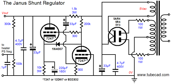
Janus Regulator -
Sounds good
Dead quiet
Rectifier not needed
DanL
Interesting, but more high tech than I was hoping I'd have to go.
If the PT can handle the extra load, seems that adding another pi-filter stage (or two) to the end of the PSU taps would be the easiest thing to do.
Maybe, I'm not seeing the whole picture (or issue).
Looking at the voltage drops coming off those resistors I would need many repetitions to lose the 150 vdc I need to drop.
10k-ohm or even 22k-ohm resistor at the end of the PSU rail is not that unusual. As Wheezer posted, those tubes you need to power don't need much mA. Good one or two watt rated one would be fine. Just put the resistor into a pi-network, to help de-couple it from the other stages.At least, that is what I would try.
Good luck on the unit!
Edits: 07/16/14 07/16/14 07/16/14 07/16/14 07/16/14 07/16/14 07/16/14 07/16/14 07/16/14 07/16/14 07/16/14 07/16/14 07/16/14
Won't that change the voltages at the earlier filter stages too though? I have to keep the voltages the same at the existing filter stages for the line stage. I guess I need to post a schem of my power supply.
What's the load of the line stage and the phono stage?
line stage has 2 76 tubes and 2 6sl7 tubes. phono stage will have 2 6dj8 tubes.
You're only adding about 16mA to the PS if you're using 1/2 of each 6dj8.
Are you sure about running a 6dj8 with 250V on the plate?
KISS - LCR.
Get it up and running. Then add whatever finesse floats your circuit!
Already had it up and running by using a loop with 5k of resistance and pulling my b+ off of that, but it was a space heater in miniature!
I may have to just go ahead and bread board it with a separate power supply like I originally planned just to see how it sounds. Trying to get a round the high B+ fron the line stage is turning out to be way more trouble than I thought it would be.
Oh, it's 250 vdc b+, not on the plate.
Edits: 07/16/14
The dropping resistor will work fine if you put a loading resistor on it. Dropping 150 volts across a 20K dropping resistor requires a load of 7.5 mA. A 33K resistor to ground after the dropping resistor will pass 7.5mA from 250 volts. Play around with PSU Designer II.
There are also voltage regulators. One of my favorite way's to drop voltage is to rig up a big MOSFET as a source follower and use a Zener reference on the collector. (See Nelson Pass' article http://www.firstwatt.com/pdf/art_zv3.pdf ) A bit more complicated but it can be pretty good as a simple regulator for a circuit with basically constant current draw.
By the way, who does not recommend an RC filter?
I may not have explained it correctly....
My pre amp has a seperate chassis power supply that uses a tube (5r4gy) rectifier and has a LCLC filter network with a 20k/50w bleeder resistor across the 2nd 15u cap. This gives me 400 vdc for the b+ for the pre amp via an umbilical to the pre amp chassis. What I want to do is tap into the b+ on the pre amp chassis and take 250 vdc to the phono pre amp chassis for it's b+.
I was trying to model this on psuII but could not see any way to do it. Not sure how you would set it up.
It wasn't a RC filter that wasn't recommended, but rather dropping b+ voltage with a resistor. It was said that this would adversly affect sound quality from what I could find.
Not quite sure how you would set up what you described on PSUII either.
Since this appears to be a simple solution to the problem I would really like to see a drawing of how to implement it. Do you know where one can be found on the net?
Edits: 07/16/14 07/16/14 07/16/14
You don't say how much extra current your PS can supply, but you can make a very nice 255V shunt regulator for the phono pre using a CCS, a 0D3 and a 0C3 VR tube. The CCS feeds the series-connected 0D3 and 0C3 tubes from the 400V at the current needed for the stage plus the current you want to shunt, say a total of 20-30mA, the two tubes in series will regulate your voltage to 255V.
I do this for my 26 preamp by dropping a 400V supply down to 225V with a CCS, 0D3 and 0A3. I use one regulator per channel to ensure excellent channel separation, but you could also do it with one regulator for both channels. Plus they look really cool when they are lit up!

Who did the silkscreen/paint on your panels?
--------------------------
Buy Chinese. Bury freedom.
Front Panel Express. It's engraved and infilled.
Edits: 07/18/14
Are the edges of those panels silver (raw aluminum), rather than black like the faces? They don't quite look like that in the photos, which is why I asked. FPE cuts panels after they're anodized, so edges aren't finished.
--------------------------
Buy Chinese. Bury freedom.
Sounds interesting. Do you have a schematic you would be wllling to share?
My power supply transformer says it has 0.165A available. My preamp uses 2 76's, 2 6sl7's and the phono pre will have 2 6dj8s.
Edits: 07/16/14
0.165A equals 165 milli-amps (mA), not "micro-amps" as you stated up above. I wondered how any kind of tube circuit could require less than 1 mA of current and still work.
Your question provoked a lot of experienced guys to provide a variety of interesting ways to go, which is very educational for the rest of us too. Thanks.
Milli and micro will make me crazy yet!
That's one of the things that is so neat about this site; it can be very educational.
You have to add up the current demands of all parts of the two units, then make sure you have enough current from your PT and that your chokes can handle the higher current as well.
Here's a link to an article by Gary Pimm about CCS-fed VR tubes. I think you'll be able to figure it out from there.
I was hoping for a simple way too just reduce the b+, but it is beginning to look like I may have to go back to the seperate power supply for the phono preamp.
Someone else mentioned this, but the simplest way to use your existing supply is to drop voltage with an appropriately sized and watt-rated R in series, followed by a C in parallel, for a dollop of added isolation between the two stages. I don't see why that wouldn't work, but perhaps I've missed something in the discussion. All you need to know is the current draw of your phono stage, in order to calculate R.
Is there a drawing anywhere of how this would be done? I am not sure I understand how it would go together. I am all for simple; as long as it doesn't make a space heater out of my phono stage. : )
If there is anything wrong with doing it this way, anyone can jump in and let us know.
I had the impression that your B+ for the linestage is already regulated upstream. If so, you could tap voltage for the phono stage off the last node that feeds the linestage circuit, which should be at 400V, if memory serves. Then you need to have at least a ballpark idea of how much current is needed for the phono stage. Let's say it's 50mA, just for the sake of calculation. And let's say you want to drop the voltage to 250V. So, you need a resistor to go in series between the 400V node in the linestage PS to a node that feeds the phono stage. This resistor must drop 150V. Here is where Ohm's Law comes in handy. Voltage (V) = current (I, in Amperes) times resistance (R, in ohms). Rearranging the equation to solve for R, we have R = V/I or R = 150/.05 = 3000 ohms.
You also need to take into account the power, P (in Watts)= I*V = .05A*150V = 7.5W. Use at least a 10W resistor; I have used 12W Mills resistors in a similar situation. They get hot; don't worry.
Then you could place an additional filter cap in parallel with the resistor, on the phono stage side. This will afford some additional isolation of the phono stage PS from the linestage PS. 50uF or 100uF would be acceptable values, for example. More or less capacitance could also be used with various consequences.
A possible negative consequence of doing it this way is that you are now pulling that extra 50mA from the same source that you want to supply 400V to your linestage. This might drop the voltage for the linestage below 400V. What will happen depends upon the relative current demands of the two stages. But you probably could live with a slight drop in the linestage V.
I just checked and the power supply on the line stage is unregulated. Where does that leave us?
except that leaves you the possibility of inserting a constant current source/voltage regulator in between the linestage 400V and the phono stage 250V. The 150V you need to drop can best be used to allow the needed headroom for the VR. See above responses by others; there were several suggestions for how to implement a VR at the linestage/phono stage interface. Putting a CCS before the VR will also effect isolation between the two, an added bonus.
I am beginning to think that getting rid of the hum on the separate power supply for the phono might be the easiest way to go after all. Going to have to mull all this over. Thanks!
Edits: 07/17/14
Thanks for the post. I will digest all this and give it a try. Right now I can still go either way, it's just swapping a feww things around.
Not sure if my ps is regulated on the line stage, I will have to check.
Edits: 07/17/14
K and K audio sells a nice high voltage shunt regulator kit that has fully adjustable output voltage. They would work great in you application, as far as I know. They come with full documentation on how to set up for your application.
I have used them with success. I have no affiliation with them.
Post a Followup:
| FAQ |
Post a Message! |
Forgot Password? |
|
||||||||||||||
|
||||||||||||||
This post is made possible by the generous support of people like you and our sponsors:
