 |
Audio Asylum Thread Printer Get a view of an entire thread on one page |
For Sale Ads |
|
|
Audio Asylum Thread Printer Get a view of an entire thread on one page |
For Sale Ads |
98.247.132.28
In Reply to: RE: Comments on your post (sorry - a bit long) posted by Ryelands on January 27, 2017 at 09:37:32
"I feel pretty sure it's not ground loops I've cured as discussed in the Jim Brown or Bill Whitlock papers as I have no connections between system ground and safety ground."
If I remember correctly the Risch "isolators" are RC filters, right? RC's are for "type 1", aka differential mode, problems.
"Type 2" noise is a subset of the more broad set of problems known as common mode noise.
It's pretty safe to say that in general solutions for differential problems are almost completely useless for common mode issues and vise versa. All systems will have a bit of both differential and common mode noise present pretty much throughout the system. It's only a matter of how much and is it a problem? Many times the most effective solution is a bit of both differential and common mode filtering.
There is only so much that even the best power supply designer can do in design and layout to prevent emi. Mother nature disallows perfection from an emi standpoint. Unfortunately, in some cases, filters are the best option. When all that can be done in these areas has been, you are left with filters to get you the rest of the way. Filters are a necessary evil.
Henry Ott is considered one of the old masters when it comes to understanding EMC issues. Slide 16, in the link about common mode problems from power supplies, gives a visual for the power supply leakage current "ground loop" path from energy transferred via transformer inter winding capacitance and via parasitic capacitance to nearby conductive objects.
As Ott points out, in the slides but also in his several excellent books on the subject, leakage current generally responsible for causing conducted problems. Conducted problems can be handled with filters.
Though an important point to note, by my estimation, is that conducted can easily convert to radiated and vise versa under the proper conditions so getting a filter in just the right location is critical to prevent high frequency conducted problems from converting to radiated energy.
Diff mode problems are easy, you can easily see them with any oscilloscope. With common mode, not so much.
The hard part is figuring out if you have common mode problems big enough to worry about and all it's mechanisms and nature of being. With that info dealing with it is a snap. However, to set yourself up with the necessary gear and knowledge to do well at it is beyond practical for most.
Avoiding problem children at the time of new power supply purchase seems logical to me. But it's not as if the power supply companies I'm aware of are making it easy by supplying emi scan captures or anything useful like that. It's annoying.
After that, most of us are pretty much left trying stuff.
Getting into designing and having success with getting the audio system to sound better via common mode filter application is gonna be tricky for a noob. Getting the current handling capacity, as in power amp filter for example, is easy as getting enough wire gauge for the current. It's getting the filter tuned to and getting enough attenuation at the frequency of noise problem you have, putting the filters in the right spots in the proper orientation is where all the action is.
Since it's tough for us mortals to easily take a look at the problem it's about like shooting in the dark when trying to get the right filter put into the right place.
Some educated guesses are no brainers though in my opinion. For example it's almost guaranteed a PC power supply, even if covered in emi certs, will be injecting some amount of stuff back into the power line as well as onto its other cables. Playing with blocking noise from conducting out of the various cables emanating froma typical PC isn't too risky in my opinion. In fact it seems very popular on this forum now days. Your mileage may vary.
wow guess mine went a bit long too.
Follow Ups:
Many times the most effective solution is a bit of both differential and common mode filtering
Thanks for an interesting post and links. I admit that I don't get how the Type 1 / Type 2 distinction or the notion of "back-door noise" adds to what is already well known. It's been several years since I looked at Henry Ott's paper. Who knows? I might get more from it this time . . .
Whatever, JR used isolating transformers because they allow high capacitance across live and neutral without excessive leakage currents (see link). He specified split-bobbin transformers because they were easy to get for a "cheap and cheerful" project and for their low inter-winding capacitance. In practice, they get pretty hot and tend to buzz. Because I had suitable toroids to hand, I used them instead, fitting those with inter-winding screens on the input side. (Don't know why but grounding the screens on both transformers regularly trips the ELCB.)
As you suggest, designing and measuring decent filters seems beyond many audio designers, let alone us hapless DIYers. Once I grasped the importance of clean power for audio, I did much as you said and "tried stuff". After lots of "stuff", much of it discarded, my rules of thumb became:
1. A dedicated power line for digital kit and another for analogue. With care and a bit of luck, both will have lower impedances than the typical home supply (esp with UK-style "ring" circuits) and be relatively free of crud.
2. No cheapo SMPS PSUs on the above. If you need one for e.g. a data server, run it from a separate line and, if possible, connect via the latest fad, optic fibre. (It is a fad but a very effective one if done right.)
3. Instead of JR's high values of C across L&N, fit C-L-C filters between the transformers. I copied a commercial mains-rated design several cuts above those IEC socket things. By using one isolator per line-level device (~15 watts each), no real need for large coils.
Hopefully, unlike JR's circuit, I'm addressing both noise modes and, by using separate isolators & filters for each device, helping to prevent noise from one device affecting another. I don't see how a simple connecting strip or system-wide filter can do that. At least in my system, the difference that several discrete isolators makes is very apparent even though I'm using decent PSUs.
Feel free to criticise.
D
It sounds like you are already using a tuned 2 stage line filter with common mode filter first stage and differential mode filter second stage. That sounds like a really good starting place for trying out in various locations.Not that you didn't already think of it or maybe already even doing this but since you didn't mention it a couple potential tweaks for tuning the common mode performance of the first stage come to mind.
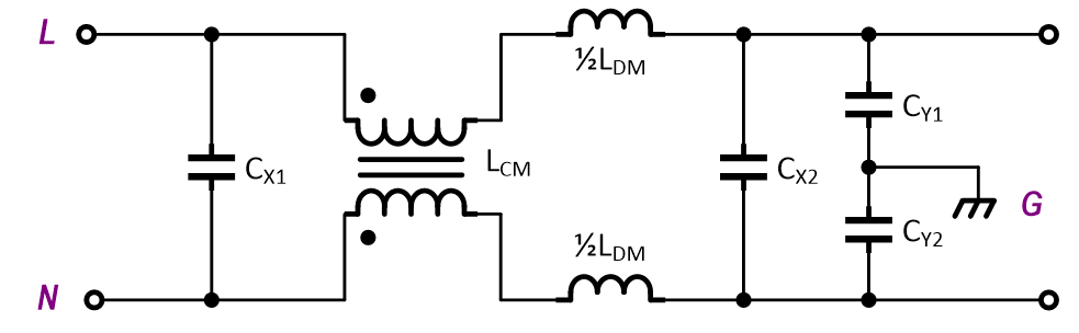
Maybe running the CLC in a balanced differential CLC configuration with respect to live and neutral will help enhance common mode rejection performance of the first stage without sacrificing the second stages differential mode performance. Ie you'd still have the same X caps spanning line and neutral but the balanced configuration would have an a separate L (but half the L as compared to an equivalent single ended version of the filter) between the caps on both the line and neutral.
You could also try adding, in a balanced manner, 2 identical and appropriately rated Y caps. One from from live to earth and one from neutral to earth. I'd try variations on where they belong, ie on the transformer primaries, transformer secondaries, after the CLC??? Some where around around 1nF ought not put you up against code violation most locales and is probably a fair place to start experimenting. Adding the Y's like this is to try and enhance common mode noise rejection of the first stage.
The only other thing I might add is that remembering to swap the order of the stages with respect to source and load to see which way works better during experimentation is another thing that may very well be worthwhile.
Edit: maybe there is a use for a damping resistor from line to neutral after the CLC to enhance it's performance.
Edits: 01/28/17 01/28/17
You could also try adding, in a balanced manner, 2 identical and appropriately rated Y caps
Thanks again for your reply. I did ponder doing as you suggest but decided I was perhaps making things a bit over-complex what with five (hopefully) separate devices. I've also got the units buried out of sight and difficult to get to. The temptation to fiddle is reduced but I might just experiment with a spare.
maybe running the CLC in a balanced differential CLC configuration with respect to live and neutral will help enhance common mode rejection performance
H/W the circuit though I didn't fit the 0v link or the 1M resistors.

Because there's a 240V > 24V transformer on the input, the filters are working at low voltage. I didn't see rating as a worry and used a pack of cheap Y-rated 220nF caps. (I'm aware that some places would need X-rated caps were they at mains potential.)
OTOH, currents are higher at the lower voltages even if no isolator is in practice passing more than about 3/4 of an amp. I guessed that 3-amp-rated Murata coils with DC resistance 0.03R would be fine. Well, they're not getting hot . . .
maybe there is a use for a damping resistor from line to neutral after the CLC to enhance it's performance
Agreed but I didn't feel confident in calculating a value so I left them out. Again, I could experiment.
D
I enjoy chatting about this stuff. No need for thanks here. I appreciate your sharing your secrets so I can see how much I'd like to try myself.
Imagine your transformer in place of the common mode choke...This is what I was envisioning Note the Y caps orientation with respect to earth. It might be worth playing with to try and increase impedance to common mode noise.
Though, regarding your filter schematic, I haven't seen anybody using an inductor on earth that way leading me to wonder what it's function in the circuit is. Presumably it can't do much until there is appreciable earth current which in my locale is strictly forbidden above a tiny level.
With double insulated, tinyish transformers, even the authorities presumably wouldn't have any problem with you not using special safety rated parts.
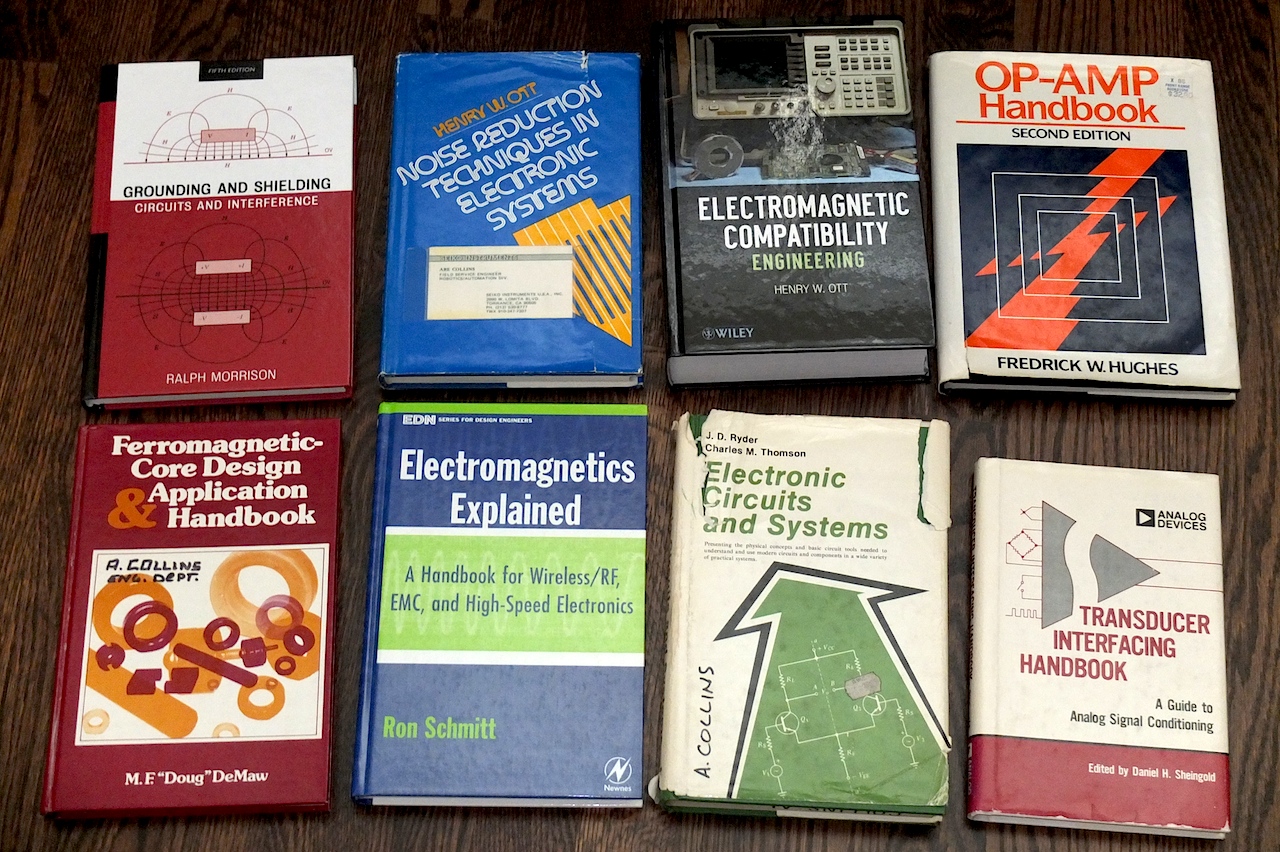
...including the two Henry Ott books in my collection. "Noise Reduction Techniques in Electronic Systems" has been a go-to reference since the 1980's.

Post a Followup:
| FAQ |
Post a Message! |
Forgot Password? |
|
||||||||||||||
|
||||||||||||||
This post is made possible by the generous support of people like you and our sponsors:
