 |
Audio Asylum Thread Printer Get a view of an entire thread on one page |
For Sale Ads |
|
|
Audio Asylum Thread Printer Get a view of an entire thread on one page |
For Sale Ads |
75.64.216.216
In Reply to: RE: Received my new M-60s today. posted by jeffreybehr on April 12, 2016 at 19:58:52
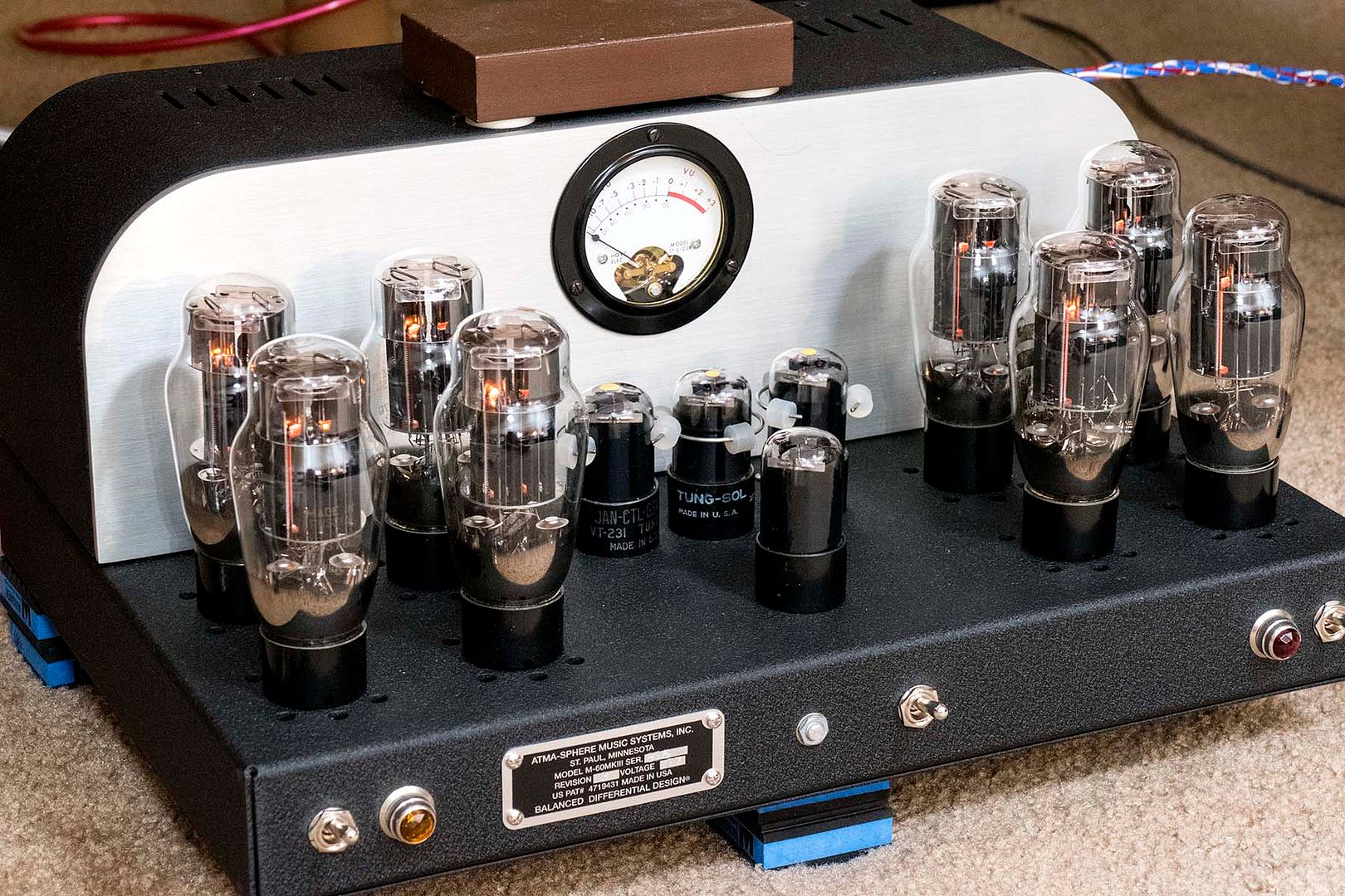
Definitely a thing of beauty. Hmmm. What is the purpose of the bridge with the 2200uF caps behind the fuses? I don't recall seeing that little circuit board either!
Follow Ups:
The little circuit board is a 2-stage CCS circuit, replacing the 6SN7 2-stage circuit of older amps. It has better performance (although the older CCS performance was excellent); because the MOSFETs have so much more gain, they really can perform better in a CCS circuit. The circuit has the added benefit of really preventing any chance of filament/cathode arc-over in the voltage amplifier circuit although that really wasn't a serious problem with 6SN7s in general.
This freed up a tube socket, which is in this case paralleled with the original 'V1' tube sections, to allow the bottom portion of the differential cascode to better drive the top portion. This yields lower distortion and slightly more headroom out of the voltage amplifier.
The other device, the bridge with the caps on it, is for blocking any DC component that may occur on the AC power line due to electric heaters and the like.
Thanks so much for the information, Ralph.
William
Straight from the Ralph's mouth, about the M-60 Mk.3.3:
1. The old 'input tube', V1, is now two input tubes in parallel, labeled V1a and V1b. V1a is in the right-rear position (see picture) while V1b is at the left-rear. These two input tubes are physically separated by the...
2. Old and new V2 which I can never remember what to call this function--it's the Voltage-gain 'top' tube in the Mk.3.1 schematic I have. This is the rear-center tube and is the one that would be replaced with the gain-reduction plugs that A-S sells.
3. The good-old V4 cathode follower is in the front of the amp.All of these in my amps are currently Tung-Sol roundplate 6SN7GTs. Those in the CF positions are my least-good tubes, low in transconductance and relatively high in microfonics--that in these CF positions are free of microfonic noise when tapped lightly with a pencil.
FWIW, even with only dozens of hours on new amps, new tubes, new Teflon-film coupling caps, etc., these amps have helped my system sound even better, particularly in transparency and spatial resolution. I'm very happy.
----------
Tin-eared audiofool, large-scale-Classical music lover, and damned-amateur fotografer.
William Bruce Cameron: "...not everything that can be counted counts, and not everything that counts can be counted."
Edits: 04/20/16
Since Ralph is using toroid power xfmrs I'll bet those are hum busters to deal with DC on the AC line.
Craig
pathologymd:
"Definitely a thing of beauty." Yes, it's certainly neater and more attractive, top and bottom, than my earlier ones were."Hmmm. What is the purpose of the bridge with the 2200uF caps behind the fuses?" I have no idea right now; don't have a current schematic. Caps are only 16VDC.
"I don't recall seeing that little circuit board either!" Me too. I think it's some kind of regulator; the devices have 3 pins. One wire is labeled 'cathode'; another is labeled 'coil', but I don't see one of those.
Output-stage caps are Nichicon 2200/200s, 35mm OD; can't see the model designation. Total OS capacitance is (6 X 2200 =) 13200uF. The schematic for a Mk.II.3 shows (6 X 1500 =) 9000uF. My old Mk.3.1 with large-PS option had (12 X 1800 =) 21600uF. I'm fantasizing about substantially improving the quality of those caps. I have 24 BlackGate VK-series 470/160s for (12 X 470 =) 5640uF per amp; probably I'll use something larger in the 1st-two cap. stages of a CRCRC filter. I also have 16 BG VK 150/350s to replace those axial-lead caps in the front-end HV supply.
We'll see.
----------
Tin-eared audiofool, large-scale-Classical music lover, and damned-amateur fotografer.
William Bruce Cameron: "...not everything that can be counted counts, and not everything that counts can be counted."
Edits: 04/13/16
Unless I'm mistaken, Ralph is liking the idea of a solid state constant current source. There are a great many plus'. Though I can't remember what they are?.
The biggest advantage, and this is huge, it frees up a 6SN7. Your M60 now has two input tubes, like the MA-1, I think?.
If I'm not mistaken, this drops distortion to really low levels.
It still has four front-end 6SN7s, and AFAIK, they're configured the same way as they were in the Mk.IIs.
----------
Tin-eared audiofool, large-scale-Classical music lover, and damned-amateur fotografer.
William Bruce Cameron: "...not everything that can be counted counts, and not everything that counts can be counted."
I've been trying to think?
If the CCS is now solid state, what would Ralph use that spare tube for?
I looked closely at your 'inards' picture.
If you look closely, the signal wire from the XLR connection goes to a tag strip.
From there the signal goes through two input resistors. These are attached to V2.
There are two wires which connect those two input points to V4, also input points.
If someone else could look at the picture, that would be much appreciated.
If someone else could look
The MA2s that I repaired years ago had paralleled tubes for the bottom part of the cascode diff. So it looks like the two side tubes are the lower part of the cascode, the middle tube is the upper part of the cascode, and the front tube is the cathode follower/driver tube.
Craig
Post a Followup:
| FAQ |
Post a Message! |
Forgot Password? |
|
||||||||||||||
|
||||||||||||||
This post is made possible by the generous support of people like you and our sponsors:

