I am probably just stoking the flames but in a recent thread started by Dimitry there were some "negative" comments about active crossovers. I maintain that an active crossover, properly designed, is superior to an speaker level xo. Just taking a commercial crossover unit and twisting the dials is not going to do it but if care is taken to simulate the original crossover design, the results will outperform the speaker level crossover every time. Also the cost of an active xo can be very competitive with biamping at the speaker level with upgraded components. IMHO biamping with a speaker level crossover is of no or limited benefit.
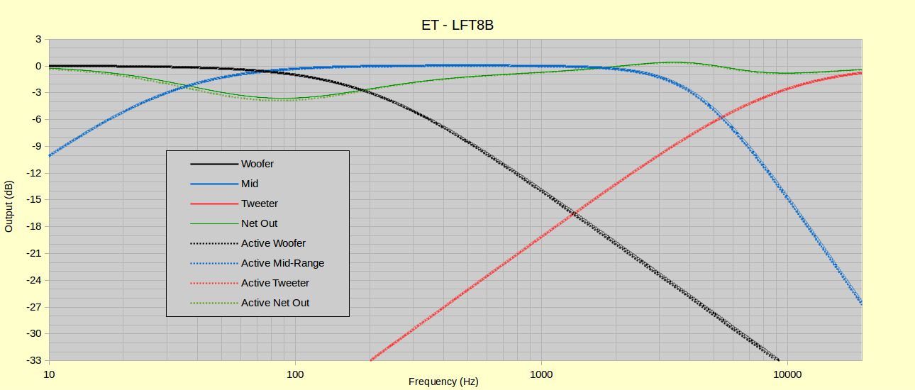
In any case here is a Bode diagram of the OEM LFE8b and an active triamp crossover which I designed. As one can see, there is no difference in the curves. I was extremely impressed with the Eminent Technology manual which went into great detail concerning the crossover and speaker parameters -- unlike another manufacturer who will remain anonymous.
To actively biamp the LFE8b, two 1st order filters are required - a woofer LP at 200 hz and a mid-tweeter HP at 30 Hz. This probably can be accomplished with a relatively cheap analog commercial crossover and certainly with a miniDSP. Of course some minor wiring changes in the OEM crossover would be required but this is well within the ability of a "newbie".
Triamping is a tad more difficult. It requires a 1st order HP filter at 9100 (10K will do) for the tweeter and a 2nd order LP filter at 4100 for the mid-driver. The 2nd order filter has a Q of 0.67 which would not be possible with the "dial-in" crossovers but a standard Butterworth (Q=.71) shoud give acceptable results. A DIY, Marchand XM-44 or miniDSP would be up for the task of an exact simulation.
Edits: 10/11/15 10/11/15Follow Ups:
- Active crossover for ET-LFT8b: FMOD RCAs? - Dimitry 10:21:25 10/12/15
(1)
- In Reply to: RE: Active crossover for ET-LFE8b posted by neolith on October 11, 2015 at 09:36:47
What about those inexpensive FMOD RCA "bullets" that you can get in many cross-over values?
The maker doesn't supply the impedance information on the devices. My amps are 150 Kohm and 35 Kohm - I am not sure I will get the target frequency...
If these are low input impedance, my 1.2 Kohm output tube preamp will not drive them properly.
- RE: Active crossover for ET-LFT8b: FMOD RCAs? - Davey 12:19:36 10/12/15
(0)
- In Reply to: RE: Active crossover for ET-LFT8b: FMOD RCAs? posted by Dimitry on October 12, 2015 at 10:21:25
The FMOD filters used resistor/capacitor combinations quite a bit lower in value to minimize deviations as a result of varying load resistances.
Unfortunately this maximizes deviations as a result of significant source output resistance.
As mentioned previously by other posters. PLLXO's simply can not be designed as stand-alone universal gadgets. Source resistance, load resistances, power amp voltage gain, etc, etc, must all be known and be incorporated into the design. Sources with high output resistance always complicate the situation.....relative to low output resistance.
Again, there are no turn-key universal solutions for PLLXO's.
Dave.
- RE: Active crossover for ET-LFT8b: FMOD RCAs? - Davey 12:19:36 10/12/15
(0)
- RE: Active crossover for ET-LFE8b - Satie 21:39:14 10/11/15
(1)
- In Reply to: RE: Active crossover for ET-LFE8b posted by neolith on October 11, 2015 at 09:36:47
You didn't mention that the mid woofer XO can be done passive line level with a single cap high pass and a resistor and cap low pass with possibly another resistor to match levels.
With such a high XO I would not bother with triamping. Once I settled on a high XO > 8khz for all my "final" variants I dropped to biamping.
- RE: Active crossover for ET-LFE8b - neolith 06:04:11 10/12/15
(0)
- In Reply to: RE: Active crossover for ET-LFE8b posted by Satie on October 11, 2015 at 21:39:14
I agree with you on biamping rather than triamping these speakers. It is why I mentioned that an approximation of the actual mid-tweeter XO would be sufficient -- a Q of .71 v .66 or fc of 9100 Hz v 10" kHz is really trivial. As far as a PLL HP filter, that certainly is a simple option but if one is going to the trouble of an active LP filter why not make the HP filter active as well. Or for that matter why not make a PLL LP filter and have a pure PLLXO.

Edits: 10/12/15
- RE: Active crossover for ET-LFE8b - neolith 06:04:11 10/12/15
(0)
- RE: Active crossover for ET-LFE8b - Dimitry 21:15:58 10/11/15
(10)
- In Reply to: RE: Active crossover for ET-LFE8b posted by neolith on October 11, 2015 at 09:36:47
ET may be an unusual case, as it purposely uses very simple cross over design with no "tricks."
The manual actually discusses active cross over as an option and recommends contacting dealers for help. I don't think a typical dealer would be much of one. However, Bruce T. will probably be very helpful - he was with me, discussing power requirements for his speaker in detail.
My problem with active is that requires you to build a cross over, and even a passive one is quite a bit of work. Then you get the choices - what brand of "special" resistor and cap to use - the highly rated ones are far from cheap. Finally, you have to rip up the internals of the speaker and eliminate/bypass the built-in circuit. This is not particularly convenient to do with many designs, and I think ET may be on of them.
I plan to replace a bypass cap on the midrange/tweeter cross over. I will let you know how difficult it is to get at it once I open the speaker by removing the woofer.
- RE: Active crossover for ET-LFE8b - neolith 06:58:13 10/12/15
(9)
- In Reply to: RE: Active crossover for ET-LFE8b posted by Dimitry on October 11, 2015 at 21:15:58
I agree that the choices of caps for a PLLXO can be overwhelming and the design takes a little work. FWIW I like tin foil REL caps and PRP resistors. I actually have a spreadsheet that will assist in the calculations both for single-ended or balanced designs. The construction is quite simple and could be done even by a novice in a few hours on a breadboard. I can give you that values for the caps and resistors if you provide the input impedances of your amps and output impedance of the preamp.
As far as tearing out the insides, it would be no more difficult than replacing the by-pass cap and a big advantage would be the elimination of that large electrolytic which I am sure is no longer to spec. Just run a jumper wire in place of the 47 uF cap, essentially by-passing the mid driver caps. Use the woofer and mid-treble input terminals.
The LFE does have a simple XO which makes design of a PLLXO or ALLXO pretty easy but the idea of multiamping is valid for any speaker. The more complicated networks with Zobels, etc are that way because of the problems with speaker level XOs and higher order filters are still easily reproduced with active analog filters or DSP solutions.
- RE: Active crossover for ET-LFE8b - Davey 07:11:35 10/12/15
(8)
- In Reply to: RE: Active crossover for ET-LFE8b posted by neolith on October 12, 2015 at 06:58:13
47uF capacitor? On the schematic I'm looking at it shows a 470uF capacitor. That's approximately a 30Hz cutoff frequency.
I guess that capacitor is essentially just for DC blocking since the driver itself provides the high-pass acoustic roll-off.Also, your simulation in the first post indicates an inverted polarity on the midrange driver. The LFT-8b schematic shows all drivers connected with the same polarity. That may be a misprint on Bruce's schematic.
Dave.
Edits: 10/12/15
- RE: Active crossover for ET-LFE8b - neolith 09:18:10 10/12/15
(5)
- In Reply to: RE: Active crossover for ET-LFE8b posted by Davey on October 12, 2015 at 07:11:35
Actually for the schematic to work the woofer and tweeter have to be inverted relative to the mid. On the schematic, the woofer is shown inverted (look carefully at the markings on the speaker pins) but not the tweeter. I did the necessary inversions to get a proper Bode. Whether the tweeter and woofer are normal with an inverted mid or the reverse situation is immaterial to my ears but some may claim they can here a difference (absolute polarity nuts).
- RE: Active crossover for ET-LFE8b - Davey 10:01:31 10/12/15
(1)
- In Reply to: RE: Active crossover for ET-LFE8b posted by neolith on October 12, 2015 at 09:18:10
Yeah, I see what you're referring to on the pictorial below (page 22), but the schematic itself doesn't agree with that. As I said, I think it's a misprint.
Dave.
- RE: Active crossover for ET-LFE8b - Davey 16:10:55 10/18/15
(0)
- In Reply to: RE: Active crossover for ET-LFE8b posted by Davey on October 12, 2015 at 10:01:31
I hadn't read the REG review of these speakers, but it seems he noticed the apparent polarity issue as well.
Second paragraph:
http://www.theabsolutesound.com/articles/eminent-technology-lft-8b-loudspeaker/?page=3
Dave.
- RE: Active crossover for ET-LFE8b - Davey 16:10:55 10/18/15
(0)
- RE: Active crossover for ET-LFE8b - josh358 09:41:55 10/12/15
(2)
- In Reply to: RE: Active crossover for ET-LFE8b posted by neolith on October 12, 2015 at 09:18:10
I used to think as you did about polarity but I was experimenting with the Etymotics and sure enough, it did. The thing is, and I'm assuming I'm not imagining things, I'm not sure whether this has to do with something the ear is doing or with the asymmetrical nature of the driver/earbud system (single balanced armature, so no XO phase distortion).
I've wondered the same thing about Maggies, which, after all, have a single-ended nonlinear B field meaning that the direction the driver moves in matters.
- RE: Active crossover for ET-LFE8b - Davey 10:18:27 10/12/15
(1)
- In Reply to: RE: Active crossover for ET-LFE8b posted by josh358 on October 12, 2015 at 09:41:55
You're coupling pretty much directly to your ears with those so any asymmetry of the transducers would tend to accentuate absolute polarity differences.
It still doesn't help a listener to know which way is "correct"....assuming there even is a correct way... for a particular recording. It's a complete crapshoot. :)Dave.
Edits: 10/12/15
- RE: Active crossover for ET-LFE8b - josh358 11:15:01 10/12/15
(0)
- In Reply to: RE: Active crossover for ET-LFE8b posted by Davey on October 12, 2015 at 10:18:27
I was astonished not only that I could tell which way was right with each recording, but could do so quickly and consistently. I would call the difference subtle but obvious, which is to say I think I could ABX it. (These were all audiophile recordings rather than multimiked ones with botched phase -- I was experimenting with the intriguing Isone VST plug in, an HRTF emulator for headphones.)
The only way I can think of to test whether it's the device or the ear can sense polarity would be to use a symmetrical transducer like an ESL in free air conditions. I think it's unlikely that the ear is sensing the polarity directly -- it's basically a rectifying device -- but I can't rule it out, since the ear is after all sensitive to static pressure. But can those nerves distinguish between low and high relative pressure? If so, it seems possible to me that it could sense something like a drum thwack -- after all, you can feel that in your gut if it's loud enough. Then too, the ear is itself an asymmetrical device and perhaps the nonlinear behavior alters the sound?
- RE: Active crossover for ET-LFE8b - josh358 11:15:01 10/12/15
(0)
- RE: Active crossover for ET-LFE8b - Davey 10:18:27 10/12/15
(1)
- RE: Active crossover for ET-LFE8b - Davey 10:01:31 10/12/15
(1)
- RE: Active crossover for ET-LFE8b - neolith 07:18:39 10/12/15
(1)
- In Reply to: RE: Active crossover for ET-LFE8b posted by Davey on October 12, 2015 at 07:11:35
Slight typo, it should have read 4.7 uF cap (the by-pass cap on the 470 mF electrolytic). Also I should have mentioned jumping the inductor on the woofer - again, just a simple replacement of the inductor with a wire.
BTW, the manual suggests using a 180 Hz HP filter (not 30 Hz) for biamping. I suspect this is because the "balancing" of inherent woofer inductance is no longer needed. Any thoughts?
Edits: 10/12/15
- RE: Active crossover for ET-LFE8b - Davey 07:39:46 10/12/15
(0)
- In Reply to: RE: Active crossover for ET-LFE8b posted by neolith on October 12, 2015 at 07:18:39
Yes, I noticed the 180Hz recommendation......obviously completely different than the stock crossover.
There are a couple of questionable directions/statements in the LFT-8b owners manual regarding bi-amping.
See my edited post above for the issue regarding midrange polarity.
Dave.
- RE: Active crossover for ET-LFE8b - Davey 07:39:46 10/12/15
(0)
- RE: Active crossover for ET-LFE8b - neolith 09:18:10 10/12/15
(5)
- RE: Active crossover for ET-LFE8b - Davey 07:11:35 10/12/15
(8)
- RE: Active crossover for ET-LFE8b - neolith 06:58:13 10/12/15
(9)
- RE: Active crossover for ET-LFE8b - hahax@verizon.net 20:13:59 10/11/15
(0)
- In Reply to: RE: Active crossover for ET-LFE8b posted by neolith on October 11, 2015 at 09:36:47
Here's another vote for properly done active crossovers. And you're correct it can't be a generic crossover that just allows choice of crossover points and roll off rate. Good modern crossovers are much more complex than that and take into account the variability of the drivers to give a correct acoustic transfer function. Each active crossover has to be designed only for the speaker system it's being used in to gain the advantages of an electronic crossover versus a passive one.
- RE: Active crossover for ET-LFE8b - Davey 13:46:46 10/11/15
(2)
- In Reply to: RE: Active crossover for ET-LFE8b posted by neolith on October 11, 2015 at 09:36:47
A conventional woofer in that system so your black, simulated curve is probably not quite correct.
However, the exact transfer function could easily be obtained with a measurement on the driver terminals.
The rest should be pretty accurate owing to the essentially resistive loads. Nice job!
Regardless, there are some people that just aren't going to be convinced with respect to line-level crossovers. And it doesn't matter how you explain it to them. :)
It's entertaining though....watching people twist themselves into pretzels trying to justify their positions.
Dave.
- RE: Active crossover for ET-LFE8b - neolith 14:19:42 10/11/15
(1)
- In Reply to: RE: Active crossover for ET-LFE8b posted by Davey on October 11, 2015 at 13:46:46
I included the inductance of the woofer in the models so the representation is pretty much in line with reality. The woofer inductance is 3.89 mH which is fairly significant since the inductor for the LP filter is 5.2 mH. I am surprised the OEM does not implement a Zobel. The manual actually discusses the rising impedance of the woofer due to its inductance.
Edits: 10/11/15
- RE: Active crossover for ET-LFE8b - Davey 19:20:06 10/11/15
(0)
- In Reply to: RE: Active crossover for ET-LFE8b posted by neolith on October 11, 2015 at 14:19:42
I can understand why they didn't include a Zobel in the stock design. It might be a good idea to include one if a user bi-amps though. That would keep the woofer amplifier from becoming completely unloaded at high frequencies. Most amplifiers probably wouldn't have an issue, but there is always the oddball.
Dave.
- RE: Active crossover for ET-LFE8b - Davey 19:20:06 10/11/15
(0)
- RE: Active crossover for ET-LFE8b - neolith 14:19:42 10/11/15
(1)
Post a Followup:
| FAQ |
Post a Message! |
Forgot Password? |
|
||||||||||||||
|
||||||||||||||
-
To view your new posting or follow-up, click on the RELOAD or REFRESH button on your browser.
This post is made possible by the generous support of people like you and our sponsors:

[
[ General ] [ Speakers ] [ Tubes ] [ Vinyl ] [ Digital ] [ Hi-Rez ] [ Video Asylum ] [ Cables ] [ Tweaks/DIY ] [ Music ] [ Films ]