 |
Audio Asylum Thread Printer Get a view of an entire thread on one page |
For Sale Ads |
|
|
Audio Asylum Thread Printer Get a view of an entire thread on one page |
For Sale Ads |
76.115.217.131
In Reply to: RE: Is Class D amplification digital? posted by stehno on November 9, 2014 at 17:07:03
Abe and others, thanks much for the info. I've always assumed class D was digital. Anyway, I email my most trusted source and here was the reply:
Hypex is absolutely correct! Switching amps, Class D. They are about as 'digital' as a light switch tuned on and off real fast. In as much as the output devices are either full on, or full off, some would say that is digital, but it is NOT related to any format of making or decoding 'digital audio' signals...That on and off is done very fast, hundreds of thousands of times a second, and the time duration of on, and off during each cycle, is them smoothed out with a filter circuit to end up with an approximation of a variable waveform that "tries" to follow, at large voltage and current, the shape of the variable [analog] input signal which is small. A tiny number of class D amps have an input receiver that can accept some formats of 'digital audio' signals, and process and translate that information, usually be a digital to analog conversion, that can then drive the to run the class D amp input node. Most class D amps are nothing more than a Pulse Width Modulated switching set.The usual means of achieving the variable pulse width is accomplished with 100% analog means, driving a differential comparator with a sawtooth ramp waveform on one input node, and the variable music signal on the other node. No digits ever! I have even done this is the lab with a few analog signal generators and a comparator input on an analog oscilloscope.
Analog,,,actually the whole friggen universe is analog! ...a lot more that a needle being drug around in a spiral groove with lots of woggles. Even the reading with laser beams of a CD or DVD or BluRay is an analog process...The "digital" part does not start until after a large number of signal processing events are done in the analog domain, including light intensity to voltage conversion and a comparitor is driven to produce an ouput that looks sort of like a stream of squared off pulses...THEN an even larger number of processes are done in digital processing to clump certain groups of pulses together, align then up in time, and in specific sequences, so that finally it can be covered into electric waveforms that approximate the music waveform.
Follow Ups:
Hi,
You must take into account both the dead time and the limited switching frequency and the comparators switching time. This severely limits the possible states.
And I would like to add that using a Ramp Waveform and Comparator is one of the ways to make an AD converter.
Calling this "Analogue" is incorrect, sorry. Unless we call everything under the sun "Analogue".
It is a single Bit modulator (AD) of low order with a power switching stage attached.
A simple way to see what is going on is to extract the error and compare the waveform and spectrum to that of an actual analogue amplifier. If the Class D Amp was "analogue" the error signals would be similar.
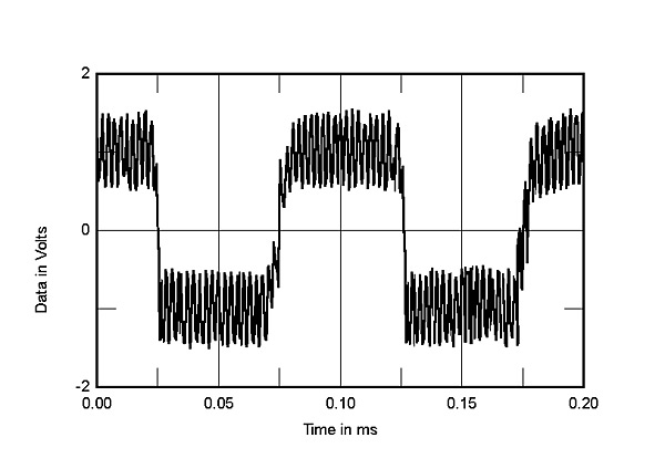
I wonder what the error signal of something like this will look like?
You must take into account both the dead time and the limited switching frequency and the comparators switching time. This severely limits the possible states.
Sure there are bounds, but he number of possible states is still infinite. PWM imposes no limitation on the number of signal values which can be represented by the pulse width. PWM is fundamentally an analog waveform. There are Class D amps such as Spectron where the signal stays analog all the way through.
PWM dimmers and motor controllers aren't digital devices either.
And I would like to add that using a Ramp Waveform and Comparator is one of the ways to make an AD converter.
Calling this "Analogue" is incorrect, sorry. Unless we call everything under the sun "Analogue".
It is a single Bit modulator (AD) of low order with a power switching stage attached.
A pulse width modulator is not the same as a delta-sigma modulator. The output of a delta-sigma modulator is a pulse train representing a bitstream where the time averaged frequency of positive values (pulse density) is proportional to the time averaged input signal. Whereas in a pulse width modulator, the duty cycle is determined by the instantaneous value of the input signal. Also, the on-off transitions at the output of a delta-sigma modulator are constrained to occur at regular intervals by a clock, whereas the on-off transitions at the output of a pulse width modulator are determined by the duty cycle. The fundamental switching frequency of a pulse width modulator is determined by the clock, but the output values are not clocked in the digital sense. So on one hand, you have a clocked stream of bits and the number of distinct signal values it can represent is limited by the integration time. It's digital. On the other hand, you have a modulated periodic waveform but it is not a clocked signal and the number of signal values it can represent is infinite. It's analog.
Post a Followup:
| FAQ |
Post a Message! |
Forgot Password? |
|
||||||||||||||
|
||||||||||||||
This post is made possible by the generous support of people like you and our sponsors:
