 |
Audio Asylum Thread Printer Get a view of an entire thread on one page |
For Sale Ads |
|
|
Audio Asylum Thread Printer Get a view of an entire thread on one page |
For Sale Ads |
131.191.158.45
Hi all,
I've got a pair of VTL MB125's that have been making some noise for many years. It was one of my very first tubed pieces of equipment, and thought that it was, for the most part, "tube noise".
This noise was more noticeable on some speakers than others, and I've lived with it for a very long time, as the noise usually was not heard at the sweet spot. But, with an addition of a new power cord, along with new(er) speakers aimed almost directly at me, I noticed the noise far more than in the past.
I had asked about this noise several weeks ago while using different speakers, and one of our fellow inmates suggested that I float the ground. So yesterday, after work, I went and bought two adapters and placed them onto the cable.
I was astonished to find that there was absolutely no noise, and I mean none, as in ZERO! It was so quiet, in fact, that I had to look to see if the amps were even on.
Needless to say, I felt quite silly thinking that I've lived with this ground problem for all these years without even realizing it. I've experienced ground issues in the past (mainly with tt cables) and thought I knew what a "ground hum" sounded like. But the noise out of the VTL's were not like that at all, so I assumed it was something else or something inherent to the amp.
I was so wrong.
I know that I should take these amps into a dealer to get them repaired, but am a bit afraid of the cost that might be attached to that work.
What I would like to know is if there's any damage that can be caused by powering the amps without a ground connected. What, exactly, does the ground in the system do?
Thanks for all your help.
'Dwebe
Follow Ups:
It's not about making everything referenced at ground potential, it's about making everything equipotential. A shield can be floating in space as long as everything with respect to that shield is referenced equipotential to it.
Precision handheld instruments are a reality, such as a DMM. No ground needed.
What is important upon connection to the DUT is that it be able to make the system equipotential still. So if the DUT is referenced to ground, the handheld will just automatically take that ground as the new equipotential of its system.
About shielding, magnetic and electrostatic, Steve is dead right on. If grounding to Earth ground is necessary to help, then something is not good enough in this equipotential system and it just so happens that it helps lower noise. In other words, it is only because of the common ground that components linked achieve an equipotential, indicating a poor system for lowering noise to its max.
To know this, one must gather up information about low noise systems such as triaxial conductors, guard traces, and such techniques. They work fine floating, grounded, or in between. It's how you make this a low noise handheld needing no ground. If stuck in a coax world, leakage current exists and that happens still with ground or no ground.
As stated correctly before, grounding is about electrical safety, not noise control for proper designed equipment. An example of improperly designed equipment is one where the secondary from an output transformer of a tube amp is left floating while the primary side is grounded. Electrostatic noise happens and arc-overs happens as these transformers do not have internal shielding (in order to get wide BW). You can ground this secondary on one side to fix it, but really the point that matters is that the secondary be placed equipotential to the primary reference, or send it to a big common buss for the whole amplifier.
-Kurt (also a person who used precision test equipment for 25 years at HP/Agilent Technologies and has measured current in PICOAMPS with no grounding)
Hi Kurt,
Question:
Does the safety equipment ground, when used on a piece of equipment, have any benefit in regards to electromagnetic interference beings it is connected to the neutral (The Grounded Conductor) at the AC grounded derived power source?
I am not speaking of the literal earth connection.... just the fact the equipment ground is connected to the neutral, which is one side of the power source.
There must be something happening there. Siemens, GE, Toshiba, Picker, all require all the conductors supplying power to their big hi-dollar X Ray units, Cat Scanner units, MRI units, to be of the same size. They always spec a separate dedicated insulated equipment grounding conductor that does not connect to any raceway, box, enclosure, ect, that connects to a terminal on their main equipment with the other end connected to the same bar as the neutral conductor at the same derived AC grounded power system.
(Example. If the feeder conductors are 3/0 then the separate dedicated equipment grounding conductor must be 3/0.)
An additional insulated equipment grounding conductor is ran along with the other conductors which is bonded to the raceway, boxes, enclosures, ect, per NEC.
Jim
note: not sure Picker is around anymore.
What I think is the issue is that there are huge currents in those machines, all of them. Much more than a big SS power amp. They probably run on 3-phase industrial power and higher primary voltages. They all need big conductors to reduce I^2*R losses and its heat generated through them. And they need matching huge conductors to balance out the voltage drops on each phase.The grounding wire is again a safety wire, big enough to carry a short of another big primary to ground and not fuse the wire itself, but something else. It goes to Neutral in the system because 3-phase systems usually are from a Y connection where the node in the center is grounded and is also neutral. The key is to get that giant current short to this major neutral with a big buss for the entire power supply. Ground is not a big deal, except that it keeps these lines at lower potential from where you stand in case of touching dangerous voltages - at least the voltage can't go up any higher than you plus the high voltage.
So again, this is not about lowering noise. In x-rays, frequencies are in some small wavelength that it's tinier than visible light. I'm sure other frequencies are in there, but still not logical to think long fat power cables can help reduce noise. Long fat irregular wires might cause some generator/load problems.
-Kurt
Edits: 07/07/10
If you remove all the grounds, use a GFI.
There should be less shock hazard than with grounded cords, and less noise too.
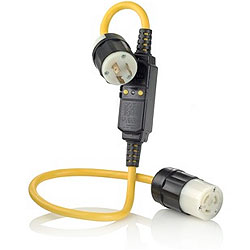
GFI or GFCI would be a great idea. But I noticed from the one or two I've checked out, they need three prong outlet and are not so cheap. At least for the units that go inline with the AC cord. The one's that replace the outlet are three-prong, though I presume they work with a two-cord device.http://www.levitonproducts.com/catalog/model_GFA15-6C.htm?sid=301CAFBEA5440B3E64B58687DA94D3E3&pid=1208
Edits: 07/01/10 07/01/10 07/01/10
Not sure what this is supposed to do. It certainly looks different than the others that I saw, which appear to connect between two items (CDP and Pre, for instance).
Is this supposed to allow for connecting a non-grounded (or lifted) amp, somehow retaining the loss of noise, plus add the safety issue back? Or is it supposed to somehow rid the noise in the line by itself?
Haven't read all the other threads yet.
The GFI is purely for protection, that if any unbalanced current flow is detected, that it halts the flow of current in a very short time, before you can be fried or electicuted basically. Typically, the ground serves to protect the cases of equipment from getting hot voltage that you can come in contact with it. The only equipment that doesn't use grounding is equipment that is 'double' insulated. Most high-end equipment has metal cases and so the ground is the only real protection from a wayward wire that can accidentally become detached.
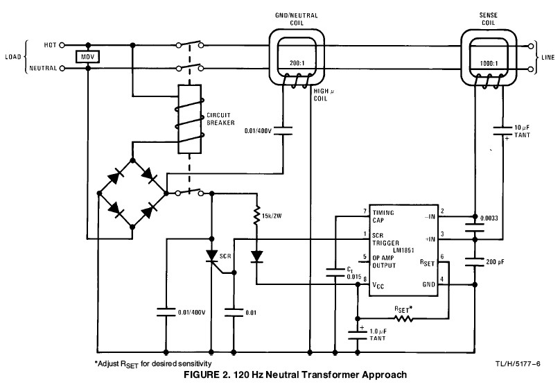
About half of the GFI that I have examined use the National Semiconductor LM1851.
As you can see, it will work with no connection to ground. I would imagine that other circuits work in a similar manner.
Has anyone run a test comparing the line noise of these devices?
Thanks!
Don't know about the noise issue, but one thing to be aware of is that GFCI's can be made to trip if the current draw is very high and/or very prolonged. Probably not going to happen in most cases, but it is something to consider...
I've spent some time today doing a bit of research (thanks for pointing me in the right direction) on the material provided here and by the manufacturer. And, from all the reading, it appears the problem potentially lies with the power in my home rather than any difficiency in the amps.
I may ultimately still have to send the amps in, but before I even get to that point, I need to eliminate the electicity in my home as the possible culprit in all this noise.
This "fix" would be really easy, if not for the potential harm to the equipment or myself that may be attributed to the removal of the ground from the amp's PC.
But with this ground removal there appears to be two completely opposite lines of thought; those who feel the benefits are outwayed by the potential for harm and those who feel that this is both the easiest and most practical way of eliminating loop hum from the system.
I spoke with three folks today (one an electrical engineer who now works at a high end shop in Seattle, another a sales associate from an on-line retailer and finally, the third, a customer service rep from PS Audio) who suggested that removing the ground was the way to go, and that safety isn't really an issue.
I spoke with the PS Audio rep last, as I was interested in what he had to say about their PC's which allow for the uncrewing and removal of the ground.
To a "T" they all said pretty much the same thing: They've never heard of anyone ever having any issues with their equipment by removing the ground.
So now, I'm a bit confused.
On the one side, those who suggest strongly to avoid removing the ground. On the other side, those who suggest strongly that that's the easiest and best fix for my current problem.
I'm planning on picking up a circuit analyzer from Home Depot on the way home this afternoon to check my outlets to see if there's any that's been miswired. If nothing's amiss, I'll try the coaxle cable remedy.
If that fails, too, then I'll just put in a different amp (solid state) into the system, as I don't recall hearing anything with that particular amp.
I guess which then brings up the question: Is a tubed amp more susceptible to line noise than a solid state amp? If the answer is no, and my Marsh makes no noise, then I guess the problem points to the VTLs.
And as for the cheater plugs, wouldn't the sale of those things be illegal if it was a known fact that adding that to any component that has a ground could lead to potential shock?
Is the potential for shock something that's remotely possible, or is it not recommended out of an over-abundance of caution?
I'm a bit reluctant to use the cheater plug now, but do not know if that's simply due to ignorance on my part.
I really wish I knew more about this stuff.
The plugs that I've used have a green tag which is "supposed" to be tied (screwed) to a grounding point on the outlet. Really, the adapter is for plugging a three-prong device into a house that has old style two-prong outlets. And still have the ground of the unit intact.
I can say from experience, that almost ALL guitar amps that I've work on which were made prior to mid-1960's, have only two prong AC lines. And the first thing I do is replace them with three-prong wiring, with the green line soldered to a solo-point on the chassis. Guitar amps are often exposed to "wet enviroments" (read: beer spills or outdoor areas which may have moisture on the ground). And it would be kinda bad not to have these high voltage devices properly grounded. As you risk having the plugged-in musician become the shortest path to ground. It's happened.
Since your amps are indoors, the risk isn't as big. But, if there is a spill of any conducting liquid near the units and you've defeated the ground wire, you risk electrocution. Also, I've found that many older houses, in order to pass visual inspections, have three-prong outlets placed in strategic areas. Then, I find that the ground portion isn't even attached to anything. This shows up using ground-fault indicating multi-outlet devices plugged into these outlets.
Yes, tube amps tend to hum more than solid-state amps. You just have to work a little harder at proper wiring. Proper placement of wires within each amp. Better soldering. Trying various IC's, etc to get the quietest & SAFEST setup.
Good luck with all that. Hum is a real BEETCH.
... plug both of your amps into the same outlet? If not, you need to try doing this. As a matter of fact, you might want to try plugging all of your stuff into one duplex outlet, if possible.
Right now, I've got the main stereo in one outlet (tt on one plug and a P300 on the other of the two) and each mono plugged into an outlet of both the right and left side of the equipment rack.
I've got one of those el cheapo (read: about 200 bucks) Monster power strips. I wanted to avoid putting the amps into those, but if I use that, I guess I can plug that into the wall and plug both amps, plus the tt into that.
I'll give that a try.
"Cheater" plugs (lifting the ground) on power cords in most all cases, are a SAFETY hazard due to electrical shock!
If you have hum the power amp is poorly designed.
Download the PASS Labs article in the link!
If he had one amp I would probably agree with your statement. He has two and we don't knw if they are plugged into the same circuit or not (potential ground loop) I have Conrad Johnson amps that are good and even plugged into the same Oyaide outlet strip I got a little hum until the grounds were lifted. Other things that could have played a part in the hum are the P300 regenerator also plugged into the same strip and perhaps the Richard Gray Parallel filter. PS Audio told me to lift their ground and it helped too. My system is dead quiet now.
ET
I thought it was time to change my signature line
So the upside is there's probably little to no damage to equipment, with the only downer being potential death.
Hmm...
I think I'll get the amps looked at.
Cheers.
nt
What I would like to know is if there's any damage that can be caused by powering the amps without a ground connected. What, exactly, does the ground in the system do?
No damage to the amps. That third pin doesn't have any relevance at all to the proper functioning of the amplifier.
Its only purpose is one of safety. It ties back to neutral at the service panel at one end, and the amplifier chassis at the other. In the event of a failure that results in the AC hot lead contacting the equipment chassis, it provides a return path back to neutral which (hopefully) prevents the chassis from having a potentially lethal voltage on it as well as allowing the breaker to be tripped or the fuse blown.
Defeating the safety ground defeats that safety feature.
Also, this should not be referred to as "lifting" or "floating" ground. That's something entirely different where the amplifier's signal reference ground is isolated from the equipment chassis and is more often a feature found on professional audio gear. It allows for ground loop issues to be addressed without resorting to defeating the safety ground.
se

Whenever you can get away with this it indicates that there is a problem with the grounding scheme of the amplifier. You really do want the amp to be grounded through the power cord, but if it causes ground loop noise it indicates that the designer has not done his homework on the grounding scheme.
Technically you don't want the amps grounded anywhere except the interconnect cable so there is the least amount of noise from ground loops.This fact is totally at odds with the issue of safety.
There are various solutions to this problem, each with its own strengths and weaknesses. Fortunately none of the solutions are expensive to implement.
You really do want the amp to be grounded through the power cord...
Eh?
I assume you mean you want the amp's chassis to have a return path back to neutral for safety purposes?
se
I think he has two monoblocks. I didn't see if anyone asked if they are plugged into the same outlet or not. Potentially there is a problem with a ground loop if they are in different outlets not on the same circuit (run)
I bi-amp and lifted grounds to get rid of that last little bit of noise and they are on the same Oyaide R-1 outlet strip.
ET
I thought it was time to change my signature line
***That third pin doesn't have any relevance at all to the proper functioning of the amplifier.
In some instances it can be an important part of a shielding system.

In some instances it can be an important part of a shielding system.
What instance would that be?
se
Noisy power supply diodes with narrow conduction angles.
And what has that to do with the safety ground?
se
...connection. In simplest form the transformer's electrostatic shield is connected to it. Many other shields are.Things like radiated and conducted susceptibility both depend on safety ground integrity. A device may very well become an FR receiver with the wire disconnected.
Just as commonly the safety ground is used to channel the ESD away from sensitive circuits.
Anyone who ever worked in instrumentation respects that wire.
Edits: 07/01/10 07/01/10 07/01/10
The transformer electrostatic shield is a very special case. It's there to provide capacitive coupling to the hot side of the primary, so as to shunt away the leakage currents that would otherwise show up at the center tap of the secondary due to capacitive coupling of same to the hot side of the primary. Charles has posted on the related subject of secondary leakage current from the center tap several times in the past, where he's recommended swapping the transformer primary leads to the configuration that minimizes these currents in the grounded center tap. I've done the same experiments and verified this trick does work. It's due to asymmetry in the capacitive coupling.
The return path of the capacitively coupled leakage current in this case is to neutral. Connecting the transformer shield to the case, and then the case to safety ground provides a path for the transformer leakage current (now dominated by that which flows through the electrostatic shield). But it's a long path from safety ground all the way back to the main service panel where neutral and safety ground connect. One could also do this at least two other ways I can think of, and neither of these ways requires connecting the chassis to safety ground. First, one could connect the electrostatic shield to safety ground, providing a path for leakage currents from the shield, to safety ground, then finally back to neutral at the service panel. The other way is to connect the shield directly to neutral, providing a much shorter path for the leakage current.
All of this is related to network theory and transformer leakage current flowing in a loop, and has nothing whatsoever to do with alleged shielding provided by connecting the chassis to safety ground. As Charles said, the inductance of such a connection is ridiculously high, providing no shielding benefit at all.
You and Dan need to read the Ott book. It directly refutes your claims. It used to be called Noise Reduction Techniques in Electronic Systems , but the latest version of the book, which came out in mid-2009, is called Electromagnetic Compatibility Engineering .
Quotable and notable> Ac power isolation transformer: There are also shielded isolation transformers that have all the features of the standard isolation transformers plus they have a full metallic shielding - of either copper or aluminum - between the primary and secondary windings. These shielded isolation transformers are referred to as electro-statically shielded isolation transformers. The electrostatic shield also called "Faraday Shield" is connected to earth ground to filter (attenuate) voltage spikes (voltage transients). These shielded isolation transformers have an attenuation ratio of 100 to 1. It also filters common mode noise. This is usually an attenuation of approximately 30 decibels. "
As usual, there is nothing like good theory and practice.
d.b
Edits: 07/02/10
As usual, there is nothing like good theory and practice.
And there's nothing like understanding something rather than just "reading words."
The AC safety ground is often referred to as "earth ground" even though its connection to literal earth ground is incidental with respect to its function as a safety ground.
What's germane in the context you bring up here is that it is connected to AC neutral, not literal earth ground. But code won't allow a direct connection of AC neutral to the equipment chassis, so instead the safety ground is used.
The purpose of the Faraday shield is to reduce the capacitive coupling between primary and secondary. Therefore its the shield's connection to AC neutral, not a literal earth ground that's of importance.
se
The data from the article I linked is real. Your argument cannot refute it, which leaves you sputtering nonsense.
Sadly, this is typical,
Sigh;
d.b.
Nisha is an Expert author for Property Auctions and uk auction list. She has written many articles like Property auctioneers, Uk property auctions, property in uk and Property auction. For more information visit: propertyauctionzone.com contact her at malar.article@gmail.com
se
which is more than I can say for some folks.
d.b.
which is more than I can say for some folks.
Got what right exactly? I don't even know what argument you were trying to make with it.
There's nothing in the "article" that settles anything with regard to a literal earth ground.
If the best you can do is reference something written by an expert on property auctions, then just give it up, Dan.
Who you going to cite next? Brittany Spears?
se
.
The data from the article I linked is real. Your argument cannot refute it, which leaves you sputtering nonsense.
What "data" was that, and what has it to do with a literal earth ground?
se
"That third pin doesn't have any relevance at all to the proper functioning of the amplifier."
You must have read all night, as today you changed your song to proving the importance of that wire. Not much of a progress, but any bit is welcome.
Turns out - the third pin DOES have relevance to proper functioning.
Thank you.
"That third pin doesn't have any relevance at all to the proper functioning of the amplifier."
You must have read all night, as today you changed your song to proving the importance of that wire. Not much of a progress, but any bit is welcome.
Turns out - the third pin DOES have relevance to proper functioning.
Y'ever hear of a thing called context, Victor?
You're being quite dishonest here.
First let's take a look at the question I was responding to.
What I would like to know is if there's any damage that can be caused by powering the amps without a ground connected.
Now let's look at what I said with the benefit of the words that preceded what you quoted but conveniently left out.
No damage to the amps. That third pin doesn't have any relevance at all to the proper functioning of the amplifier.
"Proper functioning" meaning functioning in such a way as to not cause any damage to the amplifier.
And as for a transformer's electrostatic shield is concerned, we'd already been over that. As I said, it being tied to the safety ground is purely a safety issue as direct connection of neutral is not allowed.
And that can actually create other problems because the safety ground must also be tied to the equipment chassis, so you end up defeating much of the isolation the transformer would otherwise provide.
That's why I don't care much for toroid power transformers and much prefer split bobbin laminated core transformers which provide extremely low interwinding capacitance without the need for an electrostatic shield.
se
Or so it should be.
for clouding the issue with facts.
Mea Culpa.
d.b.
***As Charles said, the inductance of such a connection is ridiculously high, providing no shielding benefit at all.
Charles, of course, stated it incorrectly. I am not sure you are aware of the fact that the conducted and radiated susceptibility tests are typically ran over the range from just several kHz all the way to 1GHz or even higher.Any discussion of quality of ground conductor is totally pointless without identifying the frequencies of interest first. There is no such thing as "ridiculously high" inductance for many frequencies in that range. It would be OK to state that the ground lead stops being an effective conductor at some frequency, but to blanket condemn it is... ahem... ridiculous.
I don't know how much work with that "ridiculously high" inductance you have done, but we have always used it to great effect, if done with proper knowledge.
I am sorry, but your suggestion of connecting the shield to the neutral displays a total lack of knowledge on subject.
As far as this passage: "I've done the same experiments and verified this trick does work. It's due to asymmetry in the capacitive coupling." - this is a common knowledge, normal design technique, nothing "trick" about it, but it has nothing to do with the subject.
Edits: 07/02/10 07/02/10 07/02/10 07/02/10
Thanks for your post Andy. I'd like to point out what I think is a typo in the second sentence. You said "It's there to provide capacitive coupling..." and I think you meant "It's there to prevent capacitive coupling..." Either that or I've had too many margaritas....
The other thing is your suggestion to connect the electrostatic shield to the neutral line. I'm not sure that would be more effective than tying it to ground, as they both go back to the service entrance panel. But it is best to avoid connecting things to the neutral line as the risk of inadvertently plugging the unit in backwards (or into a miswired outlet box) would put the shield on the "hot" line.
I don't quite understand this thread. I've seen Dan Banquer go off on odd tangents many times, but I've previously had nothing but respect for Victor and his experience.
"Thanks for your post Andy. I'd like to point out what I think is a typo in the second sentence. You said "It's there to provide capacitive coupling..." and I think you meant "It's there to prevent capacitive coupling..." Either that or I've had too many margaritas...."I was having a bit of trouble expressing that. What I meant to say was that there's strong capacitive coupling to the electrostatic shield itself from the primary, and that said capacitive coupling greatly weakens the capacitive coupling that would otherwise occur from the hot side of the primary to the center tap of the secondary (because the shield itself is tied to a potential very near to that of the center tap). Another way of looking at this is to say that the leakage current is diverted - instead of flowing from the hot side of the primary to the center tap of the secondary, it (mostly) flows from the hot side of the primary to the electrostatic shield, which has great flexibility as to how it can be connected. That is, it need not be connected to the signal common (I hesitate to say "ground" here :-)).
I think of it conceptually this way. Without an electrostatic shield, one might picture a single capacitor from the hot primary lead to the center tap of the secondary. When an electrostatic shield is added, one might picture two capacitors. One of these would be from the hot side of the primary to the electrostatic shield itself, and the second, in series with that, from the electrostatic shield to the center tap of the secondary. In the former case, the full line voltage appears between the capacitor plates (hot primary and "grounded" shield). In the latter, the electrostatic shield potential and the potential of the center tap of the secondary are almost the same, thus negligible current between them.
Does this make more sense, or do you still disagree? I realize it's still an oversimplification, but I'm just trying to capture what I think is essential.
Edits: 07/01/10
Thanks for clarifying.
In simplest form the transformer's electrostatic shield is connected to it.
Even that's purely a safety issue because safety standards prohibit it from being connected directly to neutral or to ground on the secondary side.
Things like radiated and conducted susceptibility both depend on safety ground integrity. A device may very well become an FR receiver with the wire disconnected.
Don't see that being the case.
Anyone who ever worked in instrumentation respects that wire.
In my discussions with Ott and Morrison, what I've got from them has been that outside of safety issues, it's the source of problems, not the cure to problems.
se
***Don't see that being the case.Well, like I said, anyone familiar with the field will confirm that.
Instead of just arguing, your time would be better spent reading some material on interference and ESD control. Sorry, Steve, you are completely wrong on this one.
Edits: 07/01/10
Instead of just arguing, your time would be better spent reading some material on interference and ESD control. Sorry, Steve, you are completely wrong on this one.
I did better than that, discussing the issue with both Henry Ott and Ralph Morrison.
Are you of the opinion that neither of these gentlemen know what they're talking about?
se
You might actually learn something.
d.b.
Then perhaps Victor could cite some specific reference to support his claim.
"Go read a book" is just mindless dismissal.
What book? What chapter? What section?
se
You are an Adult are you not? You do know how to use google and the library do you not?
d.b.
Steve talked to Henry Ott and Ralph Morrison and you tell Steve to go "read a book"???
Henry Ott and *especially* Ralph Morrison WROTE the damn books!
There are no higher authorities you can quote. None!
You guys are looking like fools on this one....
Steve doesn't know how to ask the right question, so yes, he would be well served to do some reading.
3.1.7 Grounding Myths
More myths exist relating to the field of grounding than in any other area of electrical engineering. The more common of these are as follows:
(...)
4. To operate with low noise, a circuit or system must be connected to an earth ground. False, because airplanes, satellites, cars, and battery-powered laptop computers all operate fine without a ground connection. As a matter of fact, an earth ground is more likely to be the cause of a noise problem. More electronic system noise problems are resolved by removing (or isolating) a circuit from earth ground than by connecting it to earth ground.
(...)
As I said, it contains several wrong points. In essence it is not much more than a cheap attention getter.
***4. To operate with low noise, a circuit or system must be connected to an earth ground.
No one has ever said that, because it is untrue. This has nothing to do with the subject.
***False, because airplanes, satellites, cars, and battery-powered laptop computers all operate fine without a ground connection.
"Operate fine" is a very strange technical term. Laptops are incredibly noisy internally, and airplanes are designed using totally different techniques from line-operated audio equipment. Anyone familiar with ignition noise in car radios knows that no ground connection is not a guarantee of anything.
***As a matter of fact, an earth ground is more likely to be the cause of a noise problem.
Nothing's "matter of fact" in this statement. While true, it is designed to divert the attention. Truth is we have to operate from ground-referenced power lines. All three of its conductors can be sources of noise. The question is not whether you can get noise injection that way, but how you deal with it.
***More electronic system noise problems are resolved by removing (or isolating) a circuit from earth ground than by connecting it to earth ground.
A totally specious argument. Who counted those cases? How did he arrive at that "more"? By polling all the EE's?
And what exactly does removing from earth ground means? Certainly eliminating the third wire does NOT accomplish that, as the neutral is just as much connected to earth. Once again - when working from the power line you are defacto connected to earth. Of the two ground conductors the safety ground is usually cleaner.
His statement confuses a typical reader into equating the battery-operated equipment with the two-conductor line operated.
***4. To operate with low noise, a circuit or system must be connected to an earth ground.
No one has ever said that, because it is untrue. This has nothing to do with the subject.
It absolutely does have to do with the subject. Dan Banquer has been making that claim for years, and you yourself essentially said just that in this very thread when you said that connection to an earth ground magically turns a piece of metal into a shield that it wouldn't be otherwise.
DB: Earth ground is cheaper than a faraday shield and in many applications works just as well.
SE: A wire stuck in the ground provides absolutely NO shielding whatsoever.
VK: That wire suddenly turns a piece of metal into a shield.
You also said that an earth ground magically "bleeds the RF energy off the cable shield."
And what exactly does removing from earth ground means? Certainly eliminating the third wire does NOT accomplish that, as the neutral is just as much connected to earth.
Yes, neutral is just as much connected to the earth ground. But unlike the safety ground, neutral is NOT connected to the equipment chassis. Therefore eliminating the third wire removes the circuit from earth ground given that in most cases the circuit's ground is tied to the equipment chassis.
Once again - when working from the power line you are defacto connected to earth.
Really?
You don't use power transformers in your stuff, Victor? You're just taking the AC mains in and directly rectifying it to power your amps and preamps?
That's pretty dangerous.
Most folks these days use power transformers which provide galvanic isolation from the power line. The only connection to earth ground would be in those instances where the safety ground is used which circumvents the galvanic isolation provided by the power transformer. Otherwise, you are decidedly not "defacto connected to earth."
se
.
I also notice that you have absolutely NOTHING to offer in response.
Just more bluff and bluster.
Pathetic.
se
No, Andy. That's all wrong.
YOU'RE NOT ASKING THE RIGHT QUESTION!

se
Steve doesn't know how to ask the right question, so yes, he would be well served to do some reading.
So what's the right question, Victor? As with my offer to Dan, I'll be happy to put it to both Ott and Morrison.
The right question is:___
Just fill in the blank.
se
.
You said I asked the wrong question. So dispense with the games and simply state what the right question is.
All you and Dan have offered so far is a bunch of hand-waving and empty claims, which is the hallmark of the quack and the charlatan.
Put up or shut up.
se
Steve talked to Henry Ott and Ralph Morrison and you tell Steve to go "read a book"???
Henry Ott and *especially* Ralph Morrison WROTE the damn books!
There are no higher authorities you can quote. None!
Nah, Charles. Henry and Ralph are both old and behind the times. Wholly ignorant of the miraculous modern discoveries about the benefits if sticking a wire in the ground.
Dan and Victor are the new authorities for the 21st Century.
Can't wait for their books to come out on the subject so I can finally enlighten myself seeing as there are currently no authoritative sources on the matter.
Amazing that in all the years we've been sticking wires in the dirt that no one else managed to discover its wonderful benefits.
We are truly in the presence of genius here. Please try and be more respectful.
se
I have explained this to Steve before, so either he likes to play games with folks who might not be as knowledgeable or he simply does not understand the theory.
d.b.
I have explained this to Steve before, so either he likes to play games with folks who might not be as knowledgeable or he simply does not understand the theory.
Stop lying, Dan.
What we had discussed previously was a LITERAL EARTH GROUND, i.e. a rod stuck in the dirt, as it related to my having said that it had no relevance at all to an audio system vis a vis grounding, shielding and noise.
You said that I didn't know what I was talking about. That I should consult an expert in the field. Specifically you cited Henry Ott who literally "wrote the book" on such issues.
So I contacted Henry Ott and he agreed with me.
"Steve you are right, there is no reason to make an earth connection in an audio system other than safety."
You didn't like that so you threw Henry under the bus and said he didn't know what he was talking about. Then you said I should consult a REAL expert in the field and cited Ralph Morrison.
So I contacted Ralph Morrison.
He agreed with me as well.
"You are right. Earth grounds are just a way of spending money." "Don't give up. You are right! The ignorance out there is amazing."
And just as with Henry, you dismissed Ralph as well.
So there you have it, folks. Don't waste your money on any of the books written by Ott or Morrison. They're just a couple of morons who don't understand the theory.
se
I guess some people still feel the need to broadcast their ignorance on the web. You're not alone; but next time ask the right question to Ott and Morrison and you will come up with the answer Victor and I give.
d.b.P.S. Be sure to tell them a screen room enclosure is earth grounded.
Remember that example I gave Steve? or have you forgotton?
Edits: 07/01/10
I guess some people still feel the need to broadcast their ignorance on the web. You're not alone; but next time ask the right question to Ott and Morrison and you will come up with the answer Victor and I give.
Oh, so I didn't ask the RIGHT QUESTION.
I see.
Tell you what, Dan, I'll give you a chance to vindicate yourself.
Tell me what the RIGHT QUESTION is and I'll be happy to pass it along to Henry and Ralph and see if they give a different answer.
se
Ask them how a screen room works, which by the way should have been obvious from my previous post.
d.b.
Ask them how a screen room works, which by the way should have been obvious from my previous post.
That's already been discussed. A screen room is grounded to earth for safety reasons as well as to prevent it from accumulating a static charge.
se
That's partially true, but it is also used as shield from EMI and RFI both trying to enter and escape.
d.b.
That's partially true, but it is also used as shield from EMI and RFI both trying to enter and escape.
Um, a Faraday shield works both ways, Dan.
*sigh*
se
Earth ground is cheaper than a faraday shield and in many applications works just as well.
Try and get a grip on that Steve
Earth ground is cheaper than a faraday shield and in many applications works just as well.
Try and get a grip on that Steve
It's not my habit to grab a steaming pile of bullshit.
A wire stuck in the ground provides absolutely NO shielding whatsoever.
Good God, Dan, you're sounding just like the quacks and charlatans you used to rail against. You outta team up with Geoff Kait.
se
See link below.
d.b.
See my reply to said post.
se
From September 24, 2003:
"There is plenty of science for those of us who dare to open and fully read things like the Belden Master Catalog, or Henry Ott, or Morrison."
Then on July 6, 2005 after both Ott and Morrison disagreed with his preconceived notions with regard to earth ground:
"I think you Ott, and Morrison have some catching up to do with a good portion of the electronics industry."
se
***A wire stuck in the ground provides absolutely NO shielding whatsoever.That wire suddenly turns a piece of metal into a shield.
It also diverts the ESD currents away from the sensitive circuits.
In addition, it bleeds the RF energy off the cable shield, so it would not get rectified by the circuit.
Other than these... yes... just a wire.
Edits: 07/01/10
> > That wire suddenly turns a piece of metal into a shield. < <
Not by itself. *If* that ground wire is connected to the *signal* ground of another component, then you may see some of the shielding effects you are talking about.
But running a wire fifty or a hundred feet to the feeder box and then another fifty or a hundred feet back to the other component is a stupid way to try to provide shielding. The inductance of the connection would be off the charts and there would be virtually no shielding at high frequencies.
Far better to link the two components with as short a length of ground wire as possible. Which is what normally happens when you connect them with an interconnect cable.
No earth ground is required, or even helpful.
Just look at the millions of Japanese receivers with two prong power cords. They seem to work just fine. No hum. No dead bodies.
***Just look at the millions of Japanese receivers with two prong power cords.That may be the key here, Charles. It is all the matter of point of reference. I did not design Japanese receivers... but I spent over 20 years designing super-sensitive world-leading instrumentation that dealt with femtoamps and nanovolts, and at one point was considered a go-to guy in one of HP divisions on subjects of RFI, EMI and ESD. This is not meant to browbeat anyone, but I have had enough of that nonsense. I am truly sorry to see you thrown your hat into this, and I am done with it.
BTW, those Japanese designers, unlike some here, know full well they would be far better off with three-conductor power cords, but they had to compete on cost alone. That they managed to achieve pretty good results with super-low-cost solutions is great credit to them. But they would have done even better with the "right" configuration.
Edits: 07/01/10 07/01/10 07/01/10 07/01/10 07/01/10
That may be the key here, Charles. I did not design Japanese receivers... but I spent over 20 years designing super-sensitive world-leading instrumentation that dealt with femtoamps and nanovolts, and at one point was considered a go-to guy in one of HP divisions on subjects of FRI, EMI and ESD.
Then you should write a book on the subject for all those poor schlubs who wasted their money on Ott's and Morrison's works.
se
***all those poor schlubs who wasted their money on Ott's and Morrison's works.
You obviously are not one of them.
i think it is stated in Ott's book as well. a potential reference is not necessary for a faraday shield but most have holes, slot etc. so it is better off to have a potentail reference and a ground connection is as good as any.
of course it does not solve all problems. i didn't say grounding but a potentail reference. since you have Ott's book handy, i'm sure you can find the relevant paragraph.
Here's something everyone can read:
Ground - A Path for Current Flow
It was written by Ott back in 1986 while he was still with Bell Labs.
Though I'm sure it's full of errors and myths so read it with a grain of salt.
se
All the stuff he writes about was a common engineering knowledge long before the article was written. In 1980 my first assignment at HP was to eliminate the crosstalk an in analytical instrument, between the variable power loads and its electrometer input. I did it by properly separating the ground planes to control the current flow patterns.So yes, a good read... you should try it.
Of course it has nothing to do with the present discussion... too bad you don't even realize that.
Edits: 07/03/10
how about page 199 of Ott' book on the grounding of sheilds.
how about page 199 of Ott' book on the grounding of sheilds.
How about personal communication with Ott directly?
The AC Power/Earth ground system is an array of long conductors, acting as antennas, picking up all kinds of noise. It is also heavily polluted with noisy AC power currents and their harmonics, from the power system and other equipment -- and completely out of your control. The earth is not a low impedance conductor. The resistance between two earthed points is rarely less than a few ohms and typically tens of ohms. The National Electrical Code allows the AC power ground to earth ground connection to have an impedance as high as 25 ohms.
Further:
If you did try to ground your product through a 6' power cord connected to the AC power outlet on the wall and then another 20' of house wiring to the earth ground, the conductors would have so much impedance (inductance) at RF frequencies that they would not keep the equipment at the same potential as the earth at all.
Let's take an example. At 20 nH per inch (typical inductance of a random wire), the twenty six feet of wire would have a total inductance of 6. 24 uH. At 50 MHz that amounts to an impedance of 1,960 ohms. So you see the futility of trying to ground your product to the earth using a wire. Even 6" of wire would have an impedance of 75 ohms at 100 MHz.
Let's look at the situation another way. The 26' of wire is over a wavelength long at 50 MHz, therefore it will act as a good antenna. If RF current flows between your product and the earth on the ground wire, it will radiate. If no RF current flows on the ground wire, you don't need the wire. Hence, at best the ground wire will be useless. At worst the ground wire will be an effective antenna and radiate. Therefore, you would be better off without it.
se
The National Electrical Code allows the AC power ground to earth ground connection to have an impedance as high as 25 ohms.
Many people read that part of the NEC code incorrectly.
NEC actually says if the ground resistance is greater than 25 ohms it shall be augmented by one additional electrode. (NEC 2008, 250.56)
The ground resistance could be 1000 ohms.... If the electrode was one 8ft ground rod then by code at least one more 8ft rod would be need to be driven. Code is satisfied....
Heheh. Clever.
Though Henry's point remains the same.
se
What he mentions are just a bunch of simple engineering facts everyone knows. Unfortunately he - and you - draw a totally incorrect conclusion from them.
If I were to follow his example and speak of cars, I would tell you they are expensive to buy and maintain, they cost a lot to refill, they break down, they get involved in accidents, they are hot in summer and freeze your ass in winter...
All that is correct, and yet to many of us having that imperfect car is whole lot more preferable to not having it.
Same here. You, OTOH, due to your lack of knowledge, are only able to see one side to the story. So what the impedance is what it is - you are unable of putting it into perspective.
Why don't you spend some time talking to engineers who have done work in that area? I mean - besides Ott. I am not asking you to disregard what he is saying, just to get the whole picture. Then you will learn how to make good use of that imperfect, but so important ground wire.
Why don't you spend some time talking to engineers who have done work in that area? I mean - besides Ott.
I have. I've also discussed this issue with Ralph Morrison.
I am not asking you to disregard what he is saying, just to get the whole picture.
If one can't get the whole picture from two of the world's most widely recognized authorities on the subject, then who exactly is one to get it from?
Certainly not from you or Dan.
Neither of you have brought one shred of illumination to this subject. All you've done is play silly games.
"You're not asking the right question."
"What's the right question?"
"Figure it out."
In my book, that makes you nothing more than a charlatan.
char�la�tan : one making usually showy pretenses to knowledge or ability
se
i think it is stated in Ott's book as well. a potential reference is not necessary for a faraday shield but most have holes, slot etc. so it is better off to have a potentail reference and a ground connection is as good as any.
Well, holes and seams in the shield are a whole other issue and grounding doesn't prevent ingress through holes and seams.
se
And I think since it's been a long time when Victor did that work he is not telling the necessary details about what you do when the frequencies are in microwave territory, the place he worked in. Only digital audio has those frequencies. A linear audio amplifier does not have any appreciable amount but can be susceptible a tiny bit to over 1 GHz noise.
When he says he worked in femto-amps and nano-volts, that's not possible in the audio to FM bands yet, I believe, but maybe. The airwaves are polluted too much to shield it down to femto-amps with grounded coaxial lines. Not on the cabling nor the power cords. I measured about SOTA measurements in 2009 on DC current at drift plus noise less than 5 pico-amps on triaxial, way ahead of coaxial for that. But at 20 GHz, the noise floor is really low and the DC leakage doesn't matter, as in working within the residual noise of the big bang as your noise problem (except in case of other such equipment present at same frequency such as from satellite signals, etc.). The only thing to apply is proper microwave theory for low noise, such as solid "ground planes" and absorption material unique to these frequencies: poly iron for one.
These are not used in audio amps, and thus Victor is bringing up old work that makes for apples to oranges comparisons. A terminated microwave power amp is not a non-terminated audio power amp at all. Even still, antenna for microwave is sent down earth grounded coaxial cable because the dish and LNA are potential lightning targets, not because it needs to be earth grounded for noise. (See those grounding splices in satellite systems on your roof to the home?) But usually the HP/Agilent equipment is all referenced to earth ground for (what else) safety, but also for power strip equipotential setups for low noise on the "ground plug". We did it for both reasons, with the second reason dubious as our SOTA equipment did better and better circuit grounding schemes within each box. Victor exited long before I, and I exited just June, 2009 working on low noise measurements, lower that Victor's equipment was.
Still, the wavelengths are so short that ground wire is silly to think about as a noise conductor except for the low FM frequency areas of the wideband NA's, SA's, sources, etc, and a trickle at 1GHz. It is good for electrostatic issues with the outside world that may damage equipment and sometimes if not perfectly designed, a boost for the noise shielding for reasons akin to holding rabbit ears a certain way to pick up channel 69 1/2. In other words, by black magic not known. So that is not an engineering approach to low noise design where if it just happens to help this time, always do it.
That is my say on the subject. Sorry Dan and Victor. The theory is not there for you wherever you came up with it.
I've been trying to go on the idea of wood amplifiers with three prong circuits and balanced power, isolation transformers and build a closed-circuit common for low noise for all equipment. Then just electrostatically drain any voltage from circuit common to ground with a resistance to ground in one location, eliminating as much as possible noise inducing loop area in the common potential down the chain. The chain matters more for low noise; the grounding issue is just in the way as it is today for performance in my opinion.
In fact, that was my last system block diagram.
-Kurt
***And I think since it's been a long time when Victor did that work he is not telling the necessary details about what you do when the frequencies are in microwave territory, the place he worked in.
This is a perfect example of... how did you put it... ah, yes! Here: "The problem here is a failure of complete communication, pure laziness, and/or forgetfullness."
You can state that, or you can say this is a wonderful example of answering the post without reading it first.
If you will indeed read my posts, it should become clear my work at HP involved DC to low frequencies. There are several key words to that effect.
A failure of communication... you can say it again! :)
No information nor explanation from you, just whining that you're right and you have the credentials. Big deal, so do I. That makes me just as big an authority. So I just cancel your opinion out. Now we have a null.
-Kurt
You wrote several paragraphs that had nothing to do with what I said - perhaps it is time to go back and for a change read before answering?
> > Now we have a null. < <
Not at all. You also have Ralph Morrison and Henry Ott on your side. I think I'd have to give your team the nod....
Not at all. You also have Ralph Morrison and Henry Ott on your side. I think I'd have to give your team the nod....
But according to the other team, Morrison and Ott are just a couple of buffoons.
se
When the statement says "add a wire to the shield floating around in space to earth ground to make this a shield" is only true, and is usually true because of grounding laws, when the system in question being shielded is indeed also earth grounded. Then you form the all important equipotential between shield and equipment.
Trying to use this shield with a handheld DMM floating will do little because the DMM is not referenced to ground in this case. EMI travels right through it magnetically, but some static can be diverted to ground or reflected back if the material is correct, so there is some help. For hum, it can help a tiny bit by absorbing some magnetically if that kind of material is there. But this is the most poor shield if it works at all.
The real solution to shield the handheld, is to reference the shield to the circuit common inside the DMM by a conductor to the DMM, not earth ground. Magnetic shielding is mostly magnetic deflection around the circuit with material like mu metal and soft iron and never needs grounding; it's a different method. EMI at other frequencies require different solutions such as conductors and RF absorbers like ferrite or on up to poly iron.
But in general, the shield is always most effective with solid shielding, close proximity to the shielded components and small for all the wavelengths. And the final thing: a connection to circuit common - not way out in left field with two different high impedance ground connections for min effectiveness.
-Kurt
Please educate me. I have all of Morrison's book plus Ott's. All are the latest edition (last time I looked) with the exception of one of Morrison's. (I forget which one. I think I have four. The one that is not the latest edition is the second latest edition.)
So please point me out to the chapter where it explains how connecting anything to earth ground makes it quieter. Thanks.
That wire suddenly turns a piece of metal into a shield.
No it doesn't.
A piece of metal shields in two ways. One is reflection loss and the other is absorption loss. Reflection loss works by way of reflecting the impinging interference due to impedance mismatch between the material and the wave. Absorption loss works by absorbing the wave energy by way of eddy currents in the material itself.
Neither of which have anything to do with whether or not the piece of metal is connected to a piece of wire stuck in the dirt, but the properties of the material itself.
Reflection loss is most effective when the material has a high conductivity/low resistivity and is most effective at shielding against electric fields. So copper would be more effective than aluminum or steel. Efficacy is only minimally increased with thickness.
Absorption loss is most effective when the material has a high permeability and is most effective at shielding against magnetic fields. So steel would be more effective than copper or aluminum. Efficacy is increased significantly with thickness
If the piece of metal fully encloses the circuit it's shielding, it doesn't need to be tied to any ground to work effectively. If it doesn't fully enclose the circuit, then it should be tied to the CIRCUIT'S ground to prevent it from capacitively coupling noise to the circuit. Tying it to a wire stuck in the ground won't help any.
Holes and seams in the metal will also determine how effective it is, but this doesn't have anything to do with whether or not it's tied to a wire stuck in the ground.
It also diverts the ESD currents away from the sensitive circuits.
It can keep a chassis from accumulating a static charge, but don't know that it would help much with regard to a discharge event. But for the sake of argument I'll grant you that.
In addition, it bleeds the RF energy off the cable shield, so it would not get rectified by the circuit.
From Ralph Morrison:
"At RF, the impedances involved along any path are very high. In fact if you do the classical impedance calculations the impedance are higher than the impedance of free space. All this means is that the grounding wire controls nothing.
The perception of draining noise in one direction is ridiculous."
se
nt
nt
especially when it is obvious that you have no real world application experience, and therefore do not understand real world applications.
Have a nice day;
d.b.
That's what quacks and charlatans like Geoff Kait, Jack Bybee et al. expect people to do. And there was a time that I thought you were above mindless shit like that but apparently I was sadly mistaken. You're no different than they are. Make empty claims, wave your hands, call those who disagree with you closed-minded idiots, etc.
You haven't been able to cite a single authoritative source to support your claims and impugn those who have established themselves as authoritative sources throughout the electronics industry.
So fuck you, Dan. You're just another charlatan as far as I'm concerned.
se
...but you are absolutely right on this one. Don't let them get you down.
...but you are absolutely right on this one. Don't let them get you down.
Thank you, Charles.
Get me down? Naaaaah. You outta know me better than that by now.
se
Could you provide a specific source to substantiate the claims you'd made, particularly with regard to literal earth ground?
I've heard various claims from Dan for years and now from you with regard to literal earth ground. The only two specific sources Dan cited were Ott and Morrison, both of whom have vehemently disagreed with his claims.
If Ott and Morrison are both just a couple of quacks who don't know what they're talking about, then who IS writing authoritatively on the subject of literal earth ground and the seeming magic it supposedly performs?
se
Listen Steve,
I don't wish to make a public mockery of your obvious lack of knowledge in regards to authoritative sources on this matter, however I will provide you with a lead to one of the most critically regarded geniuses of whom I believe Tesla himself once remarked was 'profoundly & flatulently incorrigible"
Reginald P. Balderdash III, B.Sc. A.Ss.H.Ol.E
-Bachelor Of Scientology, Calcutta (Failed)
-Associate of Specialist Sciences Houston Omni Literary Effluence
Now that I have levelled the field, keep it clean... or it simply isn't football, old chap.
Only if you get electrocuted.
Post a Followup:
| FAQ |
Post a Message! |
Forgot Password? |
|
||||||||||||||
|
||||||||||||||
This post is made possible by the generous support of people like you and our sponsors:
